Self-Balancing Robot on an ESP32: Three Control Loops
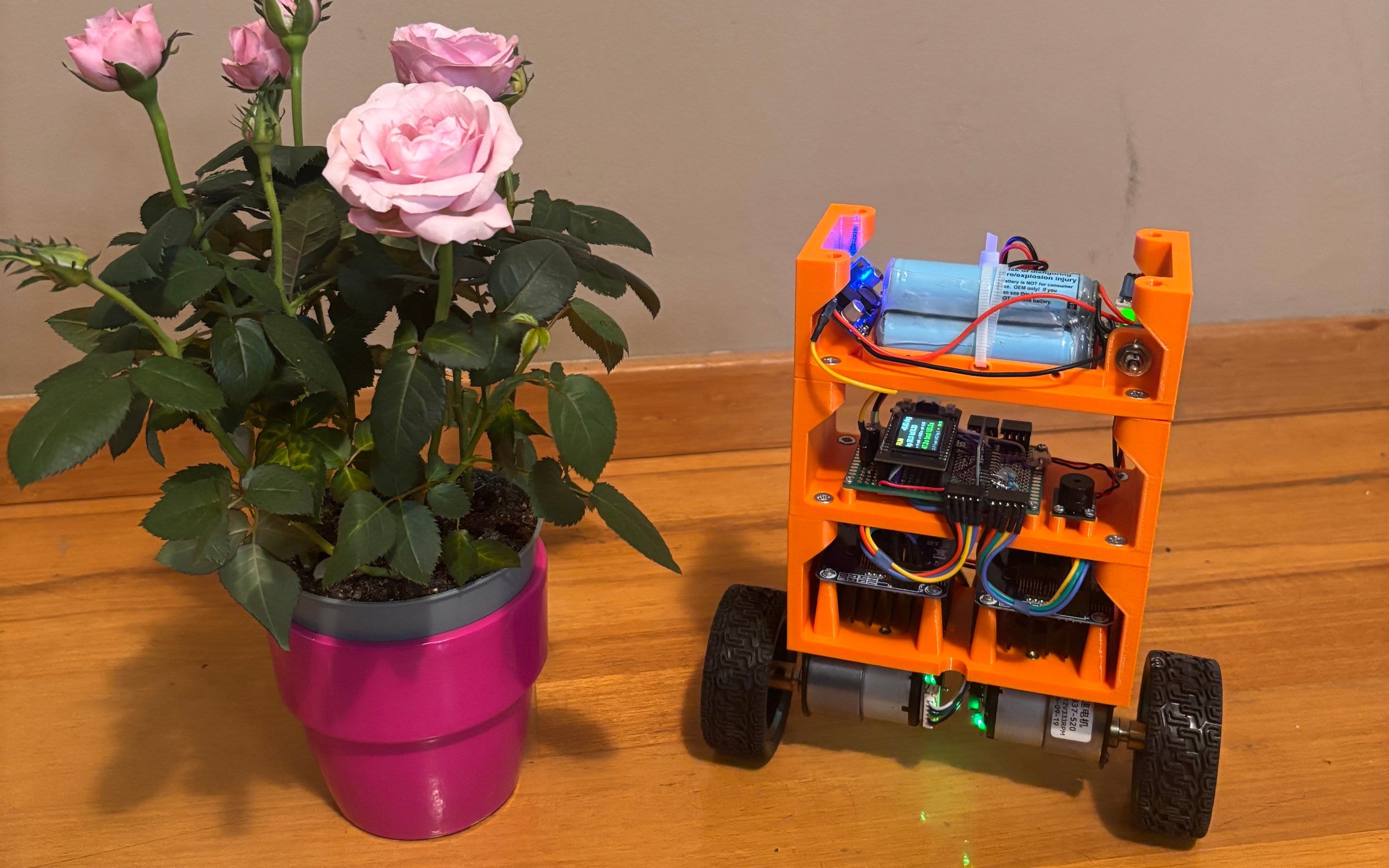
This robot just jumped off a bathroom scale and kept standing. Five days earlier it could not even stay in one place. Nothing in its hardware changed in between: the same frame, the same motors, the same sensor. Only the program changed. One control loop became two, then three, and each new loop fixed what the one before it could not do.
It is a two-wheeled self-balancing robot: a three-floor 3D-printed frame on two geared DC motors, an ESP32 board and a motion sensor. We built it to compare ways of keeping a robot upright on the same hardware, starting with the classic one, PID. This article follows the ten days from the first test to the jump in the order they happened: what is inside, how the robot knows which way is up, the three loops one by one, and what driving it over Wi-Fi taught us. The numbers come from the robot’s own logs.
The robot
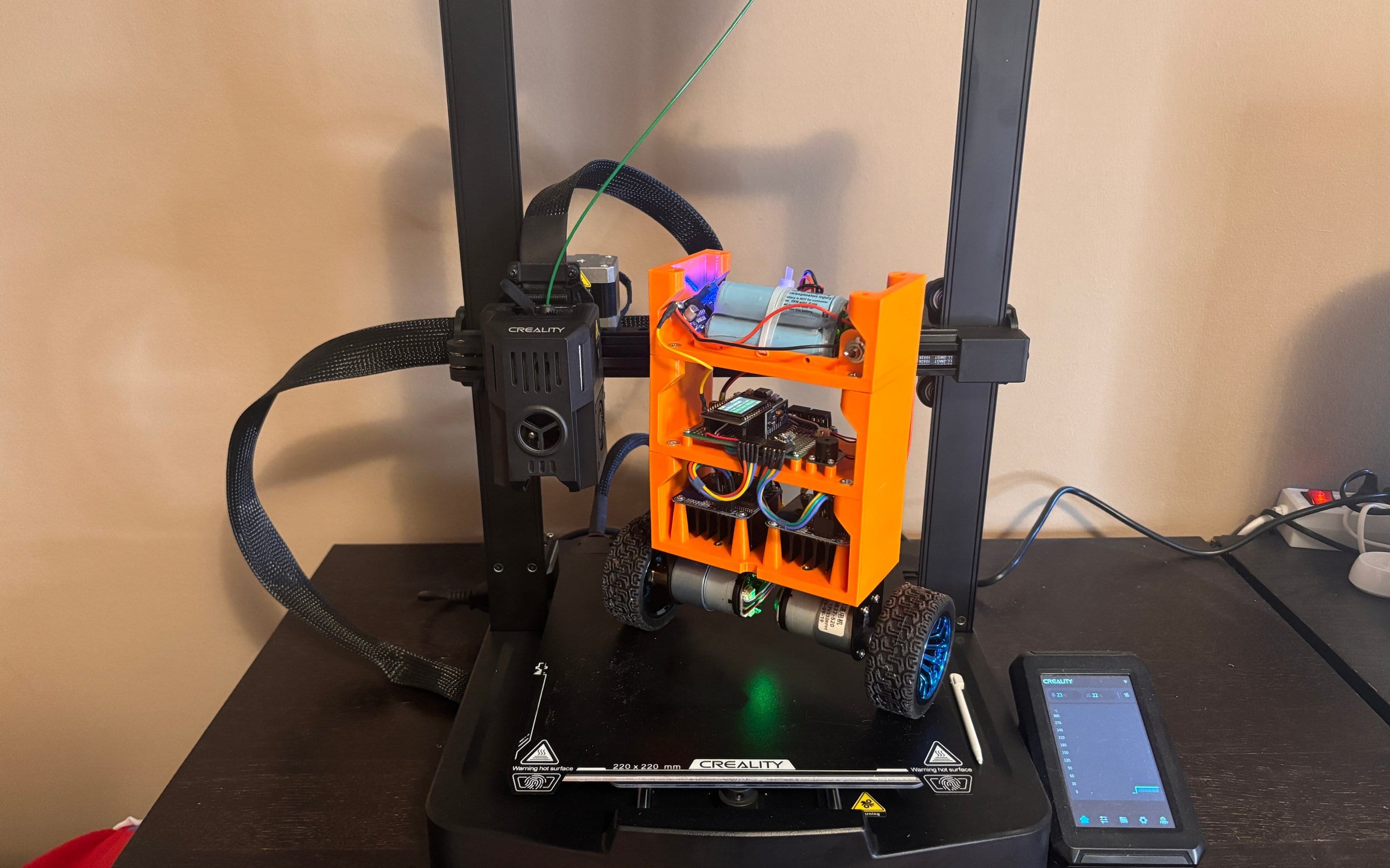
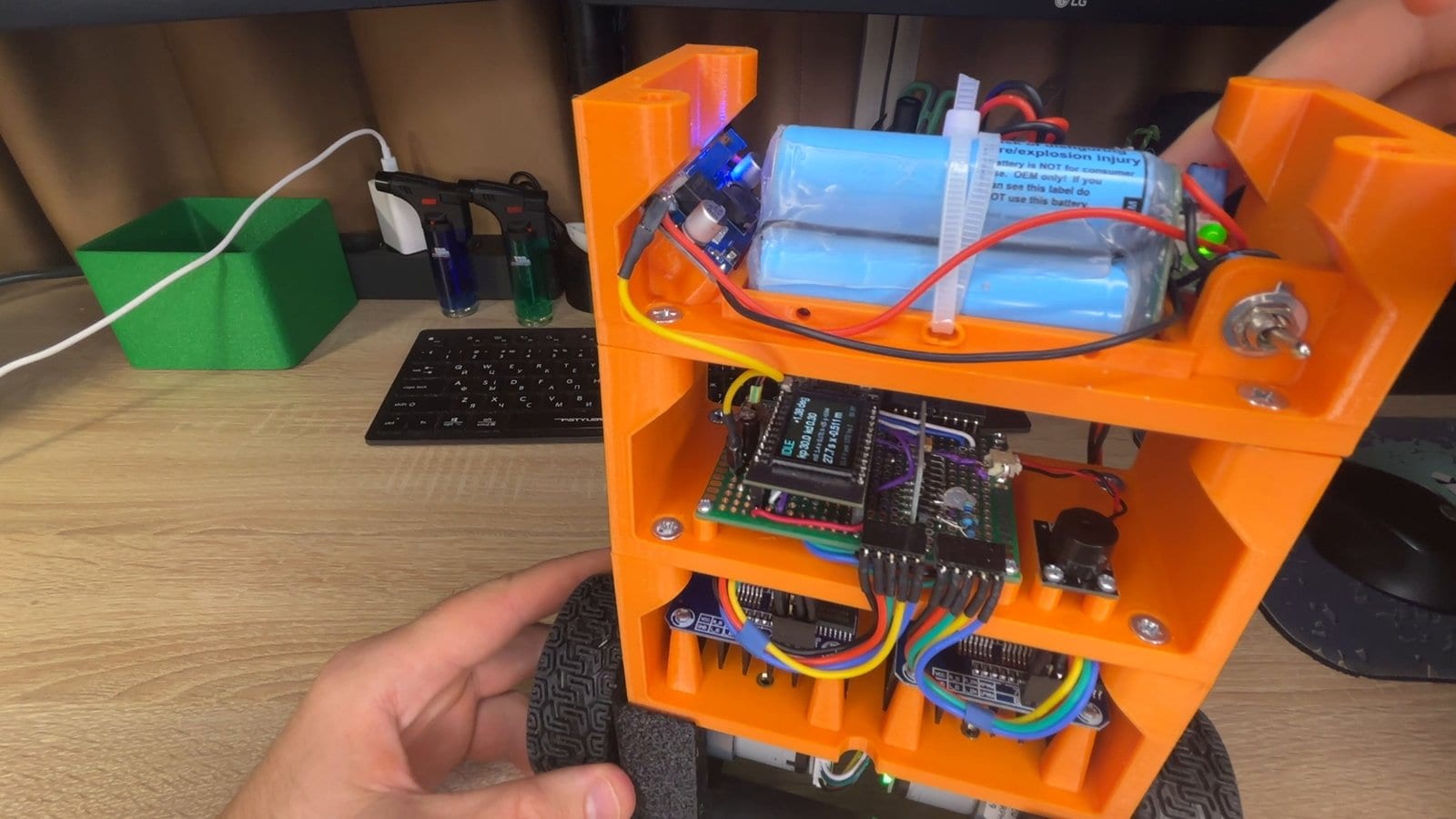
The frame is three printed floors stacked on top of each other, each a separate part. We drew it in Fusion 360 together with the bought parts, so the motors and drivers had their places before anything was printed.
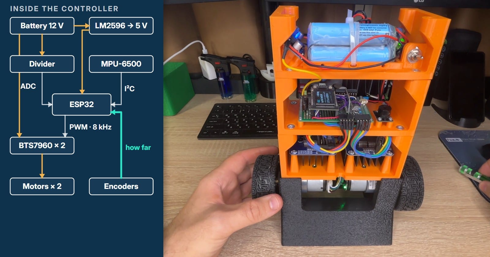
From the bottom up: the motors hang under the lowest floor on their kit brackets. The first floor holds the two motor drivers, heatsinks down. The second floor is the brain: the ESP32 board with its small screen on a perfboard, the motion sensor and a buzzer. The top floor carries a three-cell battery with its protection board, a power switch and a 5 V step-down module. The body measures 164 × 128 × 60 mm, 235 mm wide with the wheels, and the whole robot weighs 1025 g.
| Part | What we used | Its job |
|---|---|---|
| Controller | LILYGO TTGO T-Display: ESP32, two cores at 240 MHz, 1.14″ screen | One core runs the control loop, the other Wi-Fi; the screen shows the gains |
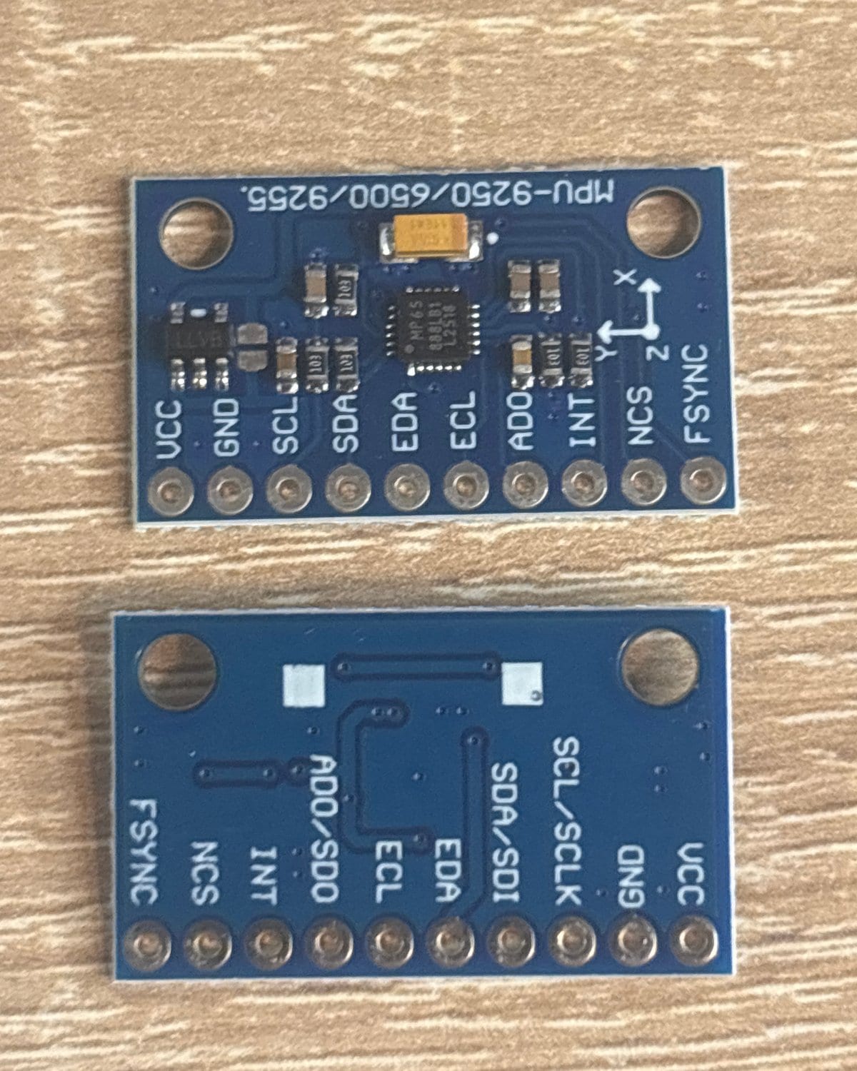
| Motion sensor | MPU-6500 on an MPU-9250/6500/9255 board, I²C at 400 kHz | Gyroscope and accelerometer, 500 samples a second |
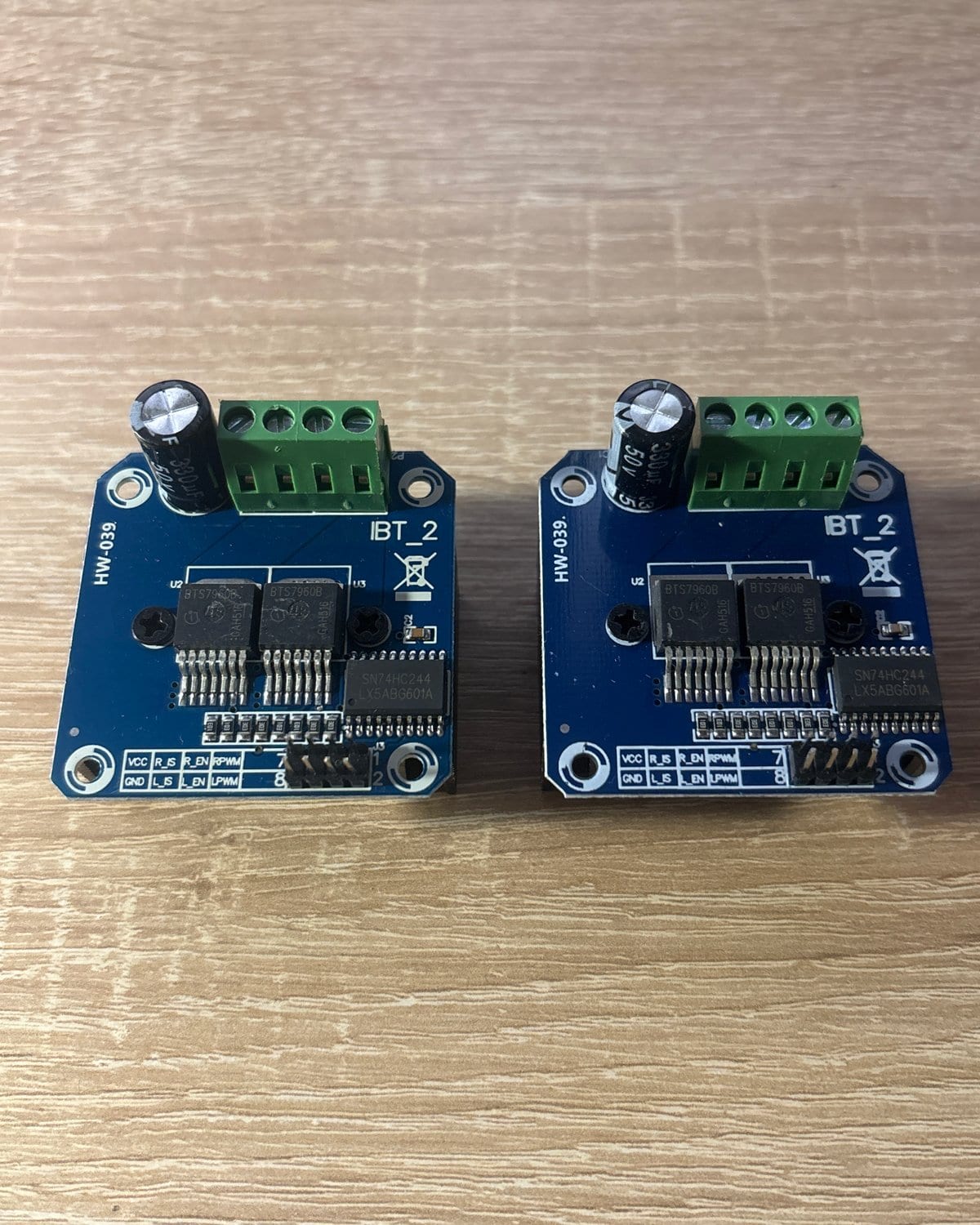
| Motor drivers | 2 × BTS7960 module (HW-039, IBT-2) | One H-bridge per motor, PWM at 8 kHz |
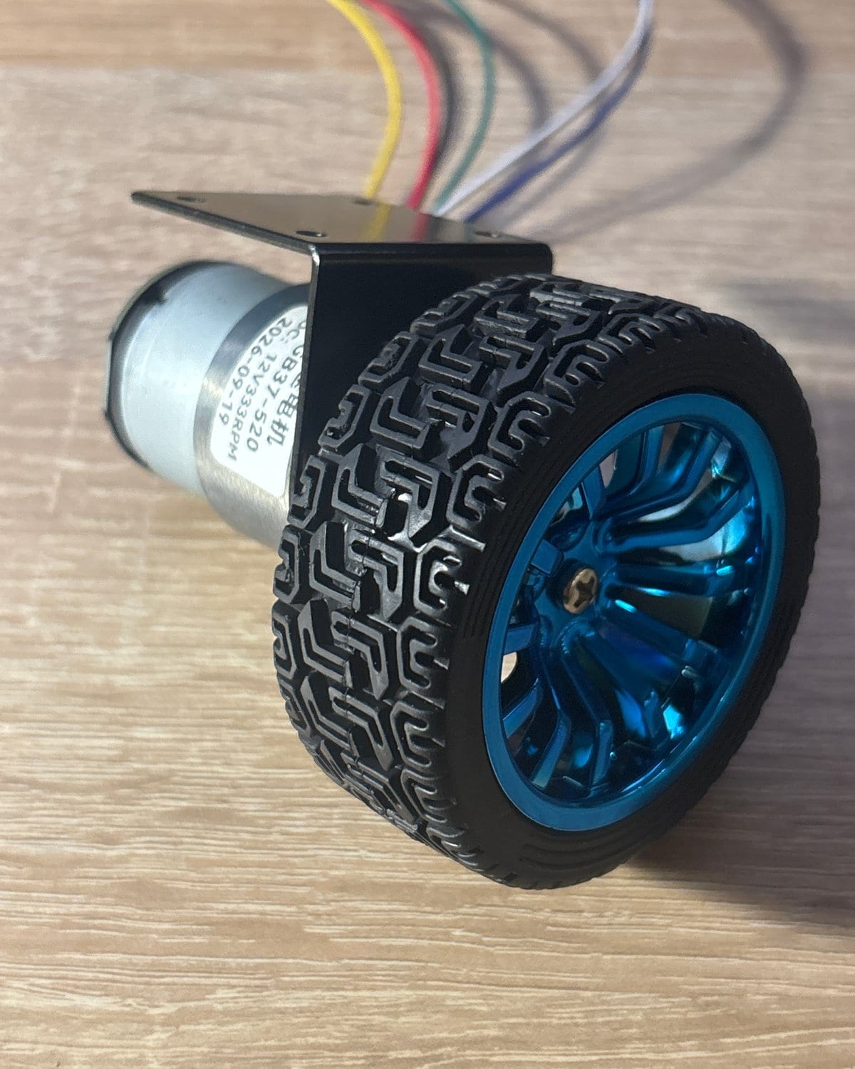
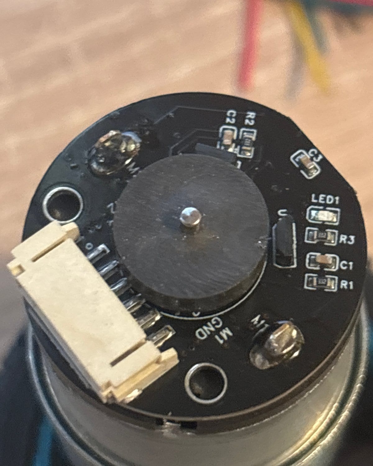
| Motors | 2 × JGB37-520, 12 V, 333 rpm, metal spur gearbox, Hall encoder | 1320 encoder counts per wheel turn, 0.16 mm of travel per count |
| Wheels | 67 mm, from the motor kit | About 210 mm of travel per turn |
| Battery | 3S 18650 pack, 11.1 V, 12.6 V full, with a BMS and a switch | Drives the motors directly; the switch cuts everything |
| 5 V supply | LM2596 step-down module | Feeds the board from the pack |
| Buzzer | Active buzzer | Three beeps when the robot arms itself |
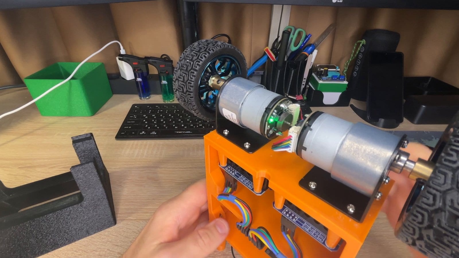
Two details of the drivetrain shaped everything that came after. The first is delay. The sensor delivers a new sample every 2 ms, and the command it leads to reaches the drivers within a millisecond, but a wheel needs about a tenth of a second to answer a change of command. The second is the gearbox: it has backlash, so after every reversal the motor turns for a moment before the wheel does.
And the two motors are not twins. Filmed from floor level, one and the same PWM command swung the far wheel by 18 mm and the near one by 8 mm. The command was identical; why the answer is not, we have not established. Left alone, the difference makes the robot slowly turn on the spot while it balances, and a small heading correction, described in the driving section, takes care of that.
Which way is up
Everything a balancing robot does depends on one number: its tilt. The MPU-6500 offers two ways to get it, and neither works on its own.
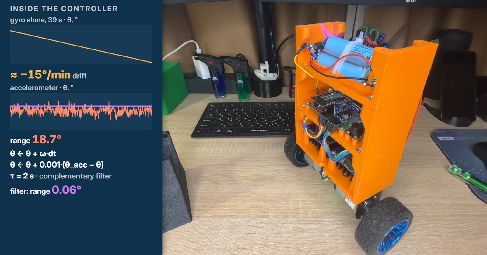
The gyroscope measures how fast the body rotates. Add its readings up every 2 ms and you get an angle that is smooth and quick, but it drifts: without correction for the gyroscope’s own offset we measured about 15° a minute. The accelerometer knows where gravity is, so its angle cannot drift, but it also feels every jolt. With the motors running, its angle jumped about over a range of 18.7°.
A complementary filter takes the good half of each. At every step the gyroscope moves the angle on, and then the angle is pulled towards the accelerometer’s reading by a tiny share of the difference, one thousandth. Put another way: 99.9 % gyroscope, 0.1 % accelerometer, which works out to a time constant of two seconds. On the bench, the filtered angle stayed within six hundredths of a degree.
In the firmware it comes down to a few lines. The sensor board is mounted on its edge, rolled by 1.4°, so before anything else the code separates the pitch rate the filter needs from the yaw rate, which the turning code uses later:
// Leaning forward, the forward axis dips below the horizontal:
// its reading is -sin(theta).
att.thetaAcc = atan2f(-(float)s.accel[1], (float)s.accel[0])
               * DEG_PER_RAD;

// The board is rolled by 1.4 deg: take pitch and yaw rates apart.
const float gx = s.gyro[0] / GYRO_LSB_PER_DPS - att.gyroBiasDps[0];
const float gz = s.gyro[2] / GYRO_LSB_PER_DPS - att.gyroBiasDps[2];
att.omegaPitch = gz * rollCos - gx * rollSin;
att.omegaYaw = gx * rollCos + gz * rollSin;

// Complementary filter: the gyroscope carries the angle from
// sample to sample, the accelerometer pulls it back to gravity.
// FILTER_K = dt / (tau + dt) = 0.002 / 2.002, about 0.1 %.
att.theta = wrapDeg(att.theta + att.omegaPitch * IMU_DT);
att.theta = wrapDeg(att.theta
                    + FILTER_K * wrapDeg(att.thetaAcc - att.theta));
The step runs to the sensor’s own clock. A hardware timer wakes the control task just before each expected sample, the task reads it and runs the whole controller, and the screen and the run log wait their turn at a lower priority. Wi-Fi lives on the other core. The pattern comes from our earlier propeller balancer, built on the same board and sensor.
Loop one: the angle
The first experiment uses a single loop that watches only the angle. It is a PID controller that runs 500 times a second, once per sensor sample, and its output is the power for both motors, in percent:
- P, the proportional part: kp = 30, so one degree of error asks for 30 % of full power.
- I, the integral: ki = 30 adds the error up over time and keeps pushing for as long as it lasts.
- D, the derivative: kd = 0.3 calms the swing. It takes the rate straight from the gyroscope instead of differentiating a noisy angle.
The target is not exactly zero. The centre of mass does not sit perfectly over the axle, so the robot balances at θ_ref = 0.3°.
float pidStep(float theta, float omegaPitch, float thetaRef,
              const Params &p, float dt, float *raw) {
    const float error = theta - thetaRef;
    const float summed = integral + p.ki * error * dt;
    integral = constrain(summed, -p.uMax, p.uMax);
    const float u = p.kp * error + integral + p.kd * omegaPitch;
    *raw = u;
    return constrain(u, -p.uMax, p.uMax);
}
The first run on the floor failed in a way the bench could not have shown. In the air every check had passed: the wheels turned, the encoders counted, the sensor read the tilt. On the floor the wheels drove away from the lean instead of under it, and the robot fell. The angle was right; what was flipped was the “forward” of the motors and the encoders. With both reversed in the configuration, the robot stood up, and with these gains it later stood for over two minutes with a standard deviation of its angle of 0.2°.
This is where a single loop runs out. During that push the body never leaned more than half a degree, and the robot rolled 27 cm and stayed there. For an angle loop that is a success, because the angle is fine. It cannot tell standing still from rolling at a steady speed: on our floor, holding a speed v takes about 4.5 % of power plus 78 % per metre per second, and the integral simply keeps whatever power the push left it with. Any speed looks like balance to it.
Loop two: speed
The second loop watches the wheels. It runs 100 times a second, reads both encoders and compares the robot’s speed with the speed it should have, zero for now. It does not touch the motors at all: its output is the angle the first loop should hold. Rolling forward? Lean back a little, and the angle loop, chasing the new angle, brakes the robot. It is a PI controller, with an integral that is clamped to the same few degrees as the output:
float pidSpeed(float vRef, float v, const Params &p, float dt,
               bool hold) {
    const float error = vRef - v;
    const float summed = hold ? speedIntegral
                              : speedIntegral + p.kvi * error * dt;
    speedIntegral = constrain(summed, -p.thetaMax, p.thetaMax);
    return constrain(p.kv * error + speedIntegral,
                     -p.thetaMax, p.thetaMax);
}
The first attempt shook five times a second. Its gain came from a model that assumed an angle loop three times weaker than the real one: kv = 10 was worked out for kp = 10, and the robot runs kp = 30. The model also ignored the tenth of a second the wheels take to answer. The cure was not a smaller gain but a calmer measurement: the speed is now averaged over 200 ms instead of 40 ms, and a 200 ms average happens to cancel a 5 Hz wobble completely.
Then the robot crept. With a purely proportional speed loop, kvi = 0, eight runs out of ten ended more than 10 cm from where they started. A small integral, kvi = 1, fixed it: in the next eleven runs none drifted further than 2.7 cm.
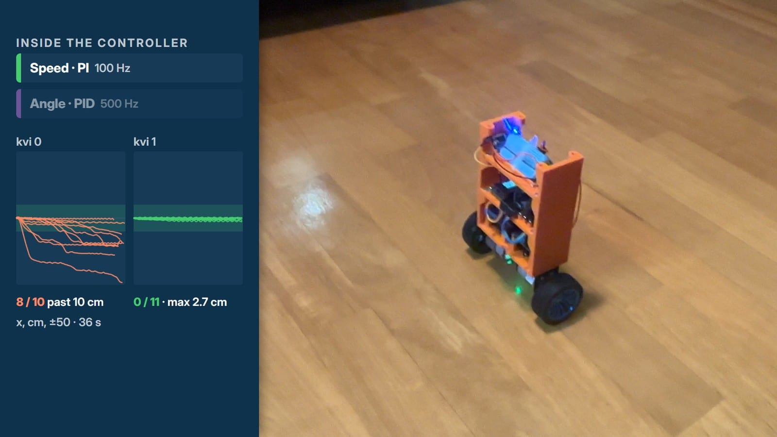
And then it did something nobody had asked it to do: pushed, it came back.
The reason is in the integral. The integral of speed is simply the distance travelled, so to keep a displaced robot at zero speed the speed integral ends up holding a small lean, about one degree per metre away from the start. That is a weak hidden spring pulling the robot home. Weak is the word: the robot returns to a band about 30 cm wide rather than to a point, and in this take two of its resting spots were 34 cm apart. Our guess is that inside the band the lean is too small to turn the gearbox through its backlash, but that is a guess, not a measurement. The take above ran with kv = 5; the stage was closed at kv = 7.
Loop three: position
The third loop remembers where the robot started, and we marked that spot with a small printed boat. Twenty times a second the loop measures the distance from home and asks the speed loop for a speed back. Its gain is kx = 1.5, so ten centimetres from home it would ask for 15 cm/s, but it never asks for more than 10 cm/s. Position sets the speed, speed sets the angle, and the angle sets the motors.
Distance comes from the encoders, corrected for the tilt: when the body leans, the wheels roll under it even if the robot as a whole stays put. Here is the cascade as it runs inside the 500 Hz step, shortened a little: the branch that lets the PC drive the robot is left out.
// Every step runs at 500 Hz: position every 25th, speed every 5th.
if (positionPhase == 0) {
    vRefNow = pidPosition(xHold + params.xRef, xNow, params);
}
positionPhase = (positionPhase + 1) % POSITION_EVERY;

if (speedPhase == 0) {
    // Hold the speed integral while a hand carries the robot away.
    const bool limited = fabsf(vRefNow) >= params.vMax;
    const bool carried = (vRefNow > 0) ? (vNow < -AWAY_M_S)
                                       : (vNow > AWAY_M_S);
    thetaOffset = pidSpeed(vRefNow, vNow, params,
                           SPEED_EVERY * IMU_DT, limited && carried);
}
speedPhase = (speedPhase + 1) % SPEED_EVERY;

thetaRefNow = params.thetaRef + thetaOffset;
percent = pidStep(a.theta, a.omegaPitch, thetaRefNow, params,
                  IMU_DT, &uCtl);
The “carried” line has a story behind it. In the first version the robot came back after a push at 20 to 46 cm/s and overshot its spot by 10 to 24 cm. The speed integral had been charging up for as long as the hand pushed, and it remembered the hand. Holding the integral whenever the position loop asked for full speed cut the overshoot to about 5 cm, but then big pushes ended 12 to 27 cm short of home. The rule that stuck holds it only while the loop asks for full speed back and the robot still moves away from home faster than 1 cm/s, which is to say while a hand is carrying it. After that, pushes of 68 and 80 cm came back to within 3 cm with no overshoot.
kx itself was chosen by moving the target point over Wi-Fi and watching the robot follow it, 36 steps for each setting:
| kx | 1 | 1.5 | 2 |
|---|---|---|---|
| Time to within 3 cm, median | 8.1 s | 4.8 s | 4.6 s |
| Largest overshoot | 2.6 cm | 3.0 cm | 5.1 cm |
| Stalls on the way | 37 | 5 | 18 |
It does not come back exactly to the boat. It stops two or three centimetres short of it or past it, held there by the same friction that let the two-loop robot settle anywhere in its band. A push of 50 cm the other way took 8.6 seconds to undo. Put the three stages side by side and the progress is plain:
| Loops | What it watches | After a push |
|---|---|---|
| 1 | Angle, 500 Hz | Rolls 27 cm away and stays there |
| 2 | Angle and speed, 100 Hz | Comes back into a band about 30 cm wide |
| 3 | Angle, speed and position, 20 Hz | Comes back to within 3 cm of its spot |
Driving it over Wi-Fi
Once the robot can hold a point, driving it is a matter of moving the point. The ESP32 joins the home Wi-Fi network, and a small Python bridge on the PC serves a web page with arrows: keyboard, gamepad or an on-screen pad. The bridge forwards the newest command to the robot over UDP twenty times a second, and the robot answers every command at once with its telemetry: angle, speed, position, heading, power, battery voltage and signal strength. While a control is held, a smoothly ramped drive speed takes the place of the position loop’s output; on release, the position loop holds the spot where the robot stopped.
Turning needed one more loop, outside the cascade. A heading loop compares the difference between the two wheels’ encoders with a set point that moves at the requested turn rate, then adds its correction to one wheel and takes it from the other. The same loop keeps the robot from turning by itself on mismatched motors. The rule is balance first: the turn only gets the power the angle loop has left over.
// Balance first: the turn gets what is left of the limit, so the
// mean of the two wheels stays the angle loop's command.
static void driveApart(float percent, float turn, float limit) {
    drivePercent = percent;
    const float room = max(limit - fabsf(percent), 0.0f);
    uTurnNow = constrain(turn, -room, room);
    motorDrive(Wheel::Left, percent - uTurnNow);
    motorDrive(Wheel::Right, percent + uTurnNow);
}The working limits are 0.35 m/s and 75° a second. The last run of 8 November lasted 150 seconds: 28 metres of driving with peaks up to 0.57 m/s, two jumps off the scale and no falls. On the first landing the body pitched to +7° for a moment, and the robot kept standing.
Not every jump went that well. Earlier that day a landing off a small ramp pitched the robot forward by 9°. To catch itself, it ran off at about a metre per second and went straight into the bed. To lean back and brake, the wheels first have to get ahead of the body, and the power command was already on its 85 % limit: at that speed there was nothing left to get them there. The limit has since been raised to 100 %, which we have not yet tried on the floor.
What keeps it from hurting itself
- It starts only on purpose. A press of a button arms it with three beeps, and it engages once it has been held within 5° of upright for 0.2 s.
- It gives up at 25°. Past that tilt it cannot recover, so the motors switch off instead of spinning the wheels against the floor.
- A watchdog of its own. A separate hardware timer drops the drivers’ enable line if no sensor sample has arrived for 10 ms. A hung I²C bus can block the control task for about a second, and a robot running blind for a second is a robot in the wall.
- Battery and sensor checks. It stops on a low pack and on a sensor fault. A lost Wi-Fi link stops only the driving: the robot comes to rest and keeps balancing.
Watch the whole build
The video tells the same story in eight and a half minutes, with the logs drawn over the footage. The player loads from YouTube only when you press it.

Pressing play loads the video from YouTube. Privacy Policy
What’s next
Ten days, three loops, one robot that stands. The PID cascade works, but it is a stack of hand-tuned pieces, and each piece was added to fix what the one before it could not do.
Next we want to replace all three loops with a single LQR controller, which computes its gains from a model of the robot instead of a person turning them one by one. After that we want to try a small neural network running on the ESP32 itself. The robot already logs its runs, partly so that such a network has something to learn from. Neither exists yet. When they do, they will face the same pushes as the PID did here, and we will publish the numbers.