Which ESP32 Should You Choose for Robotics and DIY? ESP32, S2, S3, C3, C6, and P4
Checked against official Espressif documentation on October 9, 2026. This article compares microcontroller capabilities; a particular board may expose only some of them.
For a small robot, choosing an ESP32 starts with practical questions: how to drive the motors, where to connect the encoders, whether there is enough memory for a camera, and how to send commands. CPU clock speed matters, but it cannot answer these questions on its own. For example, the C6 adds Wi-Fi 6 and a radio for Thread/Zigbee, the S3 combines two main cores with USB and camera interfaces, and the P4 focuses on computing and multimedia. The P4 itself, however, has no built-in wireless radio. [D3], [D5], [D6]
Below are six families with different capabilities useful for DIY: the original ESP32, ESP32-S2, ESP32-S3, ESP32-C3, ESP32-C6, and ESP32-P4. This is a practical selection, not a sales ranking. We will first compare the hardware resources, then look at how they affect the choice for a project.
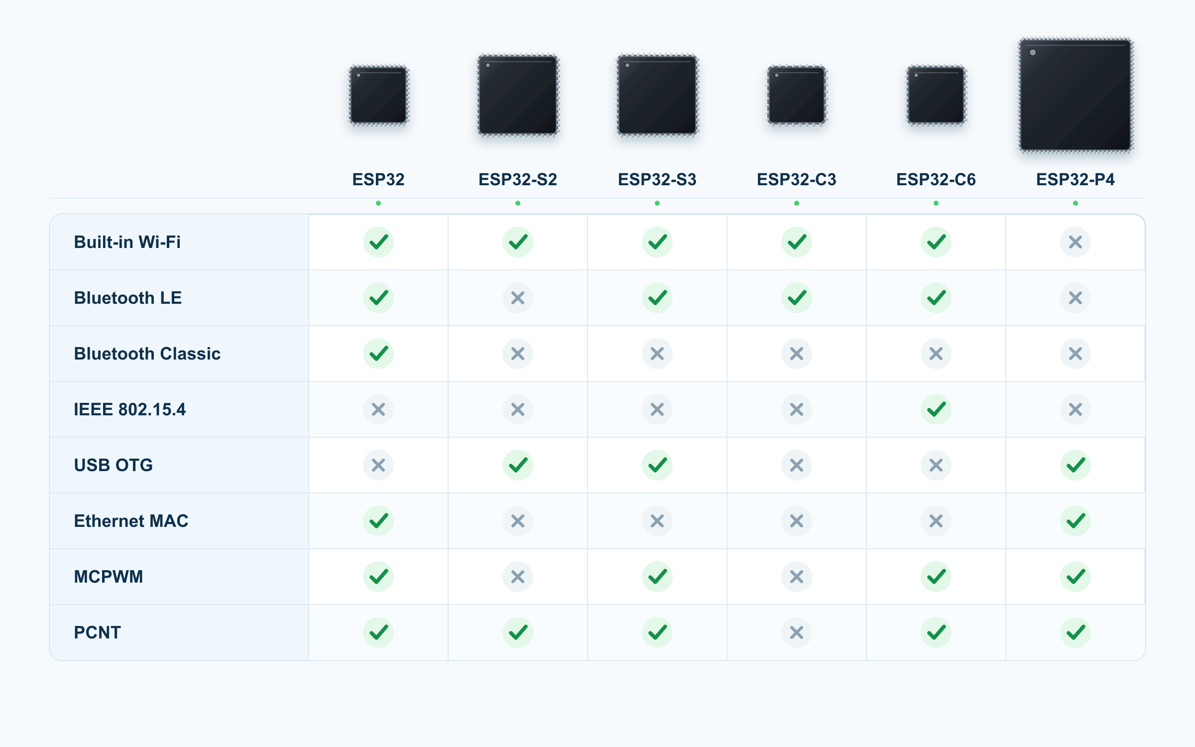
What exactly are we comparing?
A chip, a module, and a board are different levels of a product. A chip, or SoC, contains the processor, memory, and peripherals. A module combines it with additional components, such as flash, PSRAM, a crystal, and an antenna. A development board adds power circuitry, connectors, buttons, and sometimes a display or camera. Check the full part number to establish which memory is present and how much: the memory in one S3 module marked N16R8 is not a specification shared by every S3. This distinction is explained in Espressif’s platform selection guide.
A few clarifications will help when reading the tables:
- The ESP32 column uses the dual-core ESP32-D0WD-V3 as its baseline. The original family includes other variants, including the single-core ESP32-S0WD (NRND, up to 160 MHz); the family’s maximum capabilities are not guaranteed for every part. [D1]
- The P4 column covers the ESP32-P4NRW16X and ESP32-P4NRW32X, revision v3.x. The saved datasheet is marked Pre-release v0.7 / PRELIMINARY, and its electrical specifications are preliminary. The same figures should not automatically be applied to earlier P4 revisions. [D6]
- Clock speeds are maximum values; the clock speeds of two cores do not add together. HP refers to the main processing cores, while LP/ULP is a separate subsystem for low-power operation.
- GPIO and analog input counts describe the hardware resources of the chip or variant. On a board, some pins are occupied by memory, strapping pins, and installed peripherals. Multiple functions on one GPIO do not count as multiple independent pins. [D1], [D2], [D3], [D4], [D5], [D6]
- Memory capacities use the manufacturer’s notation, KB and MB. SRAM, RTC/LP memory, and PSRAM are shown separately; the heap available to an application depends on the firmware, cache, and system components.
References D1–D6 link to the official datasheets. Local copies, document versions, and section pointers are listed at the end of the article.
1. Processing and memory
| Specification | ESP32 [D1] | ESP32-S2 [D2] | ESP32-S3 [D3] | ESP32-C3 [D4] | ESP32-C6 [D5] | ESP32-P4 v3.x [D6] |
|---|---|---|---|---|---|---|
| Main CPU | Xtensa LX6, 32-bit | Xtensa LX7, 32-bit | Xtensa LX7, 32-bit | RISC-V, 32-bit | RISC-V, 32-bit | RISC-V, 32-bit |
| Main cores × maximum clock speed | 2 × 240 MHz | 1 × 240 MHz | 2 × 240 MHz | 1 × 160 MHz | 1 × 160 MHz | 2 × 400 MHz |
| Low-power coprocessor | ULP-FSM | ULP-FSM / ULP RISC-V | ULP-FSM / ULP RISC-V | No programmable ULP/LP core | LP RISC-V, up to 20 MHz | LP RISC-V, up to 40 MHz |
Hardware float operations | Single-precision FPU | No FPU | Single-precision FPU | No FPU | No FPU | Single-precision FPU |
| DSP and vector processing features | DSP instructions, including MAC | Integer multiplication and division | 128-bit vector instructions / SIMD | Integer multiplication and division | Integer multiplication and division | 128-bit vector operations, AI/DSP extensions |
| Main internal SRAM | 520 KB | 320 KB | 512 KB | 400 KB, including 16 KB used for cache | 512 KB HP SRAM | 768 KB HP L2MEM; separate 8 KB SPM |
| RTC / LP SRAM | 16 KB | 16 KB | 16 KB | 8 KB | 16 KB | 32 KB |
| Flash | External QSPI; in-package on some variants | External SPI/QSPI/OSPI; variants with in-package memory available | External SPI/QSPI/OSPI; variants with in-package memory available | External SPI/QSPI or in-package | External SPI/QSPI or in-package | External, through the MSPI controller |
| PSRAM as an extension of addressable memory | Yes, through cache | Yes, through cache | Yes, through cache, including Octal SPI | No native support | No native support | 16 or 32 MB in-package on the selected variants |
The absence of an FPU on the S2, C3, and C6 was also checked against ESP-IDF documentation: float operations on these chips are implemented in software. The FPU on the ESP32, S3, and P4 is single-precision, so double is computed in software on all six chips. That does not prevent you from writing a controller or filter, but a task with extensive floating-point computation needs execution-time measurements. [Execution speed, ESP-IDF: ESP32], [S2], [S3], [C3], [C6] [D6, §4.1.1.1]
PSRAM and flash serve different purposes. Flash stores firmware and persistent data; PSRAM expands working memory. For the original ESP32, the datasheet allows up to 8 MB of external RAM, but the window that can be mapped at one time is limited to 4 MB. Thus, “supports this much memory” and “all of that memory is accessible as one continuous array” are different claims. The S3 also has mapping limits, documented separately from the physical capacity of the connected memory. [D1, §4.1.3] [D3, §4.1.2.2]
Do not choose the C3 or C6 on the assumption that you can later add PSRAM as ordinary application heap. On the C3, only external flash is mapped through the cache, and the cache itself is read-only. The C6 datasheet likewise mentions flash only, and the manufacturer’s FAQ explicitly confirms that the C6 has no PSRAM support. Reading a separate memory chip over ordinary SPI is a different approach, not the equivalent of expanding addressable RAM. [D4, §4.1.2.2–4.1.2.3] [D5, §4.1.2.2] [PSRAM FAQ]
On the S2 and S3, ULP is an auxiliary subsystem, not another peer core for the main application. In particular, on both chips the ULP-FSM and ULP RISC-V options cannot run simultaneously. [D2, §4.1.1.2] [D3, §4.1.1.3]
2. Wi-Fi, Bluetooth, and other wireless protocols
| Specification | ESP32 [D1] | ESP32-S2 [D2] | ESP32-S3 [D3] | ESP32-C3 [D4] | ESP32-C6 [D5] | ESP32-P4 v3.x [D6] |
|---|---|---|---|---|---|---|
| Built-in Wi-Fi | 802.11b/g/n, Wi-Fi 4 | 802.11b/g/n, Wi-Fi 4 | 802.11b/g/n, Wi-Fi 4 | 802.11b/g/n, Wi-Fi 4 | 802.11b/g/n/ax, Wi-Fi 6 | None |
| Wi-Fi band | 2.4 GHz | 2.4 GHz | 2.4 GHz | 2.4 GHz | 2.4 GHz | — |
| Channel width | 20/40 MHz for 802.11n | 20/40 MHz | 20/40 MHz | 20/40 MHz | 20 MHz for ax; 20/40 MHz for n | — |
| STA / SoftAP / STA+SoftAP | Yes / yes / yes | Yes / yes / yes | Yes / yes / yes | Yes / yes / yes | Yes / yes / yes; ax specified for non-AP operation | — |
| Bluetooth Classic, BR/EDR | Yes, Bluetooth 4.2 | No | No | No | No | No |
| Bluetooth LE | 4.2 per datasheet; LE 5.0 certification exists, see explanation | No | Bluetooth 5 LE | Bluetooth 5 LE | LE, Bluetooth 5.3 certification | No |
| Bluetooth LE PHYs | LE 1M | — | LE 1M, 2M, Coded 125/500 kbit/s | LE 1M, 2M, Coded 125/500 kbit/s | LE 1M, 2M, Coded 125/500 kbit/s | — |
| IEEE 802.15.4 | No | No | No | No | 2.4 GHz, 250 kbit/s | No |
| Thread / Zigbee per datasheet | No built-in 802.15.4 radio | No built-in 802.15.4 radio | No built-in 802.15.4 radio | No built-in 802.15.4 radio | Thread 1.3 / Zigbee 3.0 | No built-in 802.15.4 radio |
Wi-Fi 6 on the C6 does not mean 5 GHz Wi-Fi. Its radio operates in the 2.4 GHz band. The datasheet also limits 802.11ax operation to a 20 MHz channel and non-AP mode: SoftAP support does not mean the C6 can create a Wi-Fi 6 access point. For n, 20/40 MHz channels are supported. The benefits of ax here include OFDMA and Target Wake Time, rather than a promise of laptop-class peak throughput. [D5, Features → Wi-Fi]
The maximum PHY rate in the radio specifications is not the useful-data throughput of TCP, MQTT, or HTTP. Comparing controllers by the “Mbit/s” figure alone therefore tells you little: the radio mode, stack, and application all affect the result. To measure real throughput, Espressif provides an iperf example, and its Wi-Fi guide explains which stack settings throughput depends on. [Wi-Fi performance, ESP-IDF] [iperf example]
The Bluetooth version label on the original ESP32 has a catch. The current datasheet lists BR/EDR and LE under specification 4.2. The manufacturer has also announced LE 5.0 certification, but its FAQ explicitly states that the chip does not support the new LE 5.0 features. That certification alone is no reason to credit it with LE 2M or Coded PHY support. Those PHYs are explicitly listed in the S3, C3, and C6 datasheets. [D1], [D3], [D4], [D5] [Bluetooth FAQ]
If a project depends on Bluetooth Classic, for example the SPP profile, that is a separate selection requirement. BLE uses a different set of protocols and profiles; the label “Bluetooth 5” alone does not imply Classic compatibility. Among the six main families here, only the original ESP32 supports Classic. Beyond those six, the picture is changing: the S31 is discussed below. [ESP-IDF Bluetooth overview] [Classic profiles, including SPP]
ESP-NOW is an Espressif protocol for exchanging data without connecting to a conventional Wi-Fi network. It uses the Wi-Fi radio rather than a separate radio block. It is an option worth considering for remote controls, telemetry, and sensors. A P4 on a board does not, by itself, provide ESP-NOW: a separate radio chip and suitable software integration are required. [ESP-NOW overview] [ESP-NOW in ESP-IDF] [D6]
Matter is an application-layer protocol, so there is no separate hardware item called a “Matter radio.” Espressif offers Matter over Wi-Fi and Thread. The C6 has an 802.15.4 radio for Thread, while Wi-Fi models can support Matter-over-Wi-Fi solutions; actual support depends on the SDK and device configuration. Zigbee and Thread use 802.15.4 but remain different stacks. The C6 datasheet specifies Thread 1.3; in January 2025, Espressif announced Thread 1.4 interoperability certification for the C6. A single C6’s ability to work with several protocols also does not imply several independent radio channels: Wi-Fi, BLE, and 802.15.4 coexist on one antenna and one 2.4 GHz radio path. [Introduction to ESP-Matter] [Thread 1.4 certification] [D5, Product Overview]
3. Peripherals: what you can connect
The SPI row counts user-accessible GP-SPI controllers, excluding controllers that serve flash/PSRAM. LP interfaces are listed separately because they may have different limitations. MCPWM counts refer to peripheral units, PCNT counts to counter units, and LEDC counts to PWM outputs. These quantities are not interchangeable.
| Specification | ESP32 [D1] | ESP32-S2 [D2] | ESP32-S3 [D3] | ESP32-C3 [D4] | ESP32-C6 [D5] | ESP32-P4 v3.x [D6] |
|---|---|---|---|---|---|---|
| GPIOs, datasheet maximum | 34, including 6 input-only | 43 | 45 | 22 or 16, depending on variant | 30 in QFN40 / 22 in QFN32 | 55 |
| GP-SPI | 2 | 2 | 2 | 1 | 1 | 2 + LP-SPI |
| UART | 3 | 2 | 3 | 2 | 2 + LP-UART | 5 + LP-UART |
| I²C | 2 | 2 | 2 | 1 | 1 + LP-I²C | 2 + LP-I²C |
| I²S | 2 | 1 | 2 | 1 | 1 | 3 + receive-only LP-I²S |
| ADC: units × resolution; inputs | 2 × 12 bits; 18 inputs | 2 × 12 bits; 20 inputs, see note | 2 × 12 bits; 20 inputs | 2 × 12 bits; 6 hardware inputs, ADC2 limitation applies | 1 × 12 bits; 7 inputs | 2 × 12 bits; 14 inputs |
| DAC | 2 × 8 bits | 2 × 8 bits | None | None | None | None |
| Capacitive touch inputs | 10 | 14 | 14 | None | None | 14 |
| LEDC: PWM outputs | 16 | 8 | 8 | 6 | 6 | 8 |
| MCPWM: units | 2 | None | 2 | None | 1 | 2 |
| PCNT: counter units | 8 | 4 | 4 | None | 4 | 4 |
| RMT: channels | 8, configurable as TX/RX | 4, configurable as TX/RX | 4 TX + 4 RX | 2 TX + 2 RX | 2 TX + 2 RX | 4 TX + 4 RX |
| General-purpose timers | 4 × 64 bits | 4 × 64 bits | 4 × 54 bits | 2 × 54 bits | 2 × 54 bits | 4 × 54 bits |
| DMA | DMA in several peripherals | DMA in several peripherals | GDMA, 5 TX + 5 RX | GDMA, 3 TX + 3 RX | GDMA, 3 TX + 3 RX | Multiple DMA controllers, including GDMA and 2D-DMA |
| TWAI / CAN | 1 × CAN 2.0 | 1 × CAN 2.0 | 1 × CAN 2.0 | 1 × CAN 2.0 | 2 × CAN 2.0 | 3 × CAN 2.0 |
| USB OTG, host/device | None | Full-Speed, 12 Mbit/s | Full-Speed, 12 Mbit/s | None | None | High-Speed 480 Mbit/s + Full-Speed 12 Mbit/s |
| Separate USB Serial/JTAG | No | No | Yes | Yes | Yes | Yes |
| SD/MMC/SDIO host | Yes | No | Yes | No | No | Yes |
| SDIO slave | Yes | No | No | No | Yes | No |
| Built-in Ethernet MAC | 10/100 Mbit/s | None | None | None | None | 10/100 Mbit/s |
| Camera and LCD | Parallel I²S modes; displays also via SPI | DVP via I²S; LCD via I²S/SPI | Dedicated LCD_CAM: DVP, parallel RGB/I8080 | No dedicated LCD_CAM; displays via SPI | PARLIO and SPI; no LCD_CAM | LCD_CAM, MIPI CSI and DSI |
| Image-processing hardware | No suite equivalent to the P4’s | No suite equivalent to the P4’s | No suite equivalent to the P4’s | No suite equivalent to the P4’s | No suite equivalent to the P4’s | ISP, PPA, JPEG codec, H.264 encoder |
MCPWM, PCNT, RMT, and timer counts were also checked against the official soc_caps.h files in ESP-IDF v5.5.3: ESP32, S2, S3, C3, C6, P4. This verifies the hardware configuration; it does not claim that this SDK version supports every feature of every new revision. In particular, P4 v3.x capabilities come from its current datasheet. The SDK’s total SPI count should not be read as the number of free user buses; internal touch-channel counts can also include a channel that is not exposed on a GPIO. The C6’s RMT split into 2 TX + 2 RX also comes from soc_caps.h: the C6 datasheet describes four channels without assigning them a direction.
Why these differences matter for a robot
LEDC, MCPWM, and PCNT do different jobs. LEDC generates ordinary PWM and is useful for more than LEDs. MCPWM provides features for controlling power stages: synchronization, complementary signals, dead time, fault-input handling, and event capture. PCNT counts pulses and can be used to read encoders with hardware filtering. Having “PWM” on the C3 therefore does not make its peripherals equivalent to those on the S3 or C6. [D1, §4.8.7–4.8.9] [D3], [D4], [D5]
That does not mean you cannot build a robot around the C3. It can suit a simple driver with a PWM input and a small number of signals. But when choosing a controller for several motors and encoders, it is more useful to count MCPWM units, PCNT units, and required GPIOs first, then consider CPU speed. This is an engineering conclusion drawn from the table, not the result of comparative tests on complete robots.
RMT stores and generates sequences of logic-level durations, and can also receive them. It lets hardware take over some of the work involved in pulse-based protocols. On the S3, C3, C6, and P4, however, transmit and receive channels are separate; an “8 channels” entry cannot be interpreted as eight transmitters without further qualification. [D1], [D2], [D3], [D4], [D5], [D6] [soc_caps.h: S3], [C3], [C6], [P4]
TWAI requires an external CAN transceiver. The table lists CAN 2.0 controllers, not CAN FD support or ready-to-use CANH/CANL electrical ports. Similarly, the Ethernet MAC on the original ESP32 and P4 needs an external PHY and the appropriate supporting circuit. [D1, §4.8.12–4.8.13] [D6, §4.2.2.12–4.2.2.13] [TWAI in ESP-IDF]
A USB connector on a board does not necessarily mean USB OTG. On an original ESP32 board, it goes to a separate USB-to-UART bridge: the chip has no USB of its own. The built-in Serial/JTAG controller on the C3 and C6 is intended for serial communication, flashing, and debugging; it cannot become an arbitrary USB HID device or USB host. For those tasks, look at the OTG controllers on the S2, S3, and P4. On the S3, OTG and Serial/JTAG share the internal PHY: using both controllers simultaneously requires a separate solution, such as an external PHY. [D3, §4.2.1.7–4.2.1.8] [D4], [D5] [ESP-USB guide]
The absence of an SD/MMC host does not prevent you from connecting a memory card over SPI. That uses a different interface with different throughput and bus-usage constraints. [Espressif SD SPI driver]
ADC: bit depth does not replace checking the limitations
To measure battery voltage or an analog sensor, you need to understand the supported input range, calibration, and shared hardware resources as well as resolution.
- ESP32-S2: the current datasheet specifies 12 bits. Erratum ADC-112 describes an issue in the early v0.0 revision and the change in effective resolution from 13 to 12 bits in v1.0. Older descriptions of an S2 with a “13-bit ADC” therefore cannot be copied into a table without a revision caveat. ESP-IDF v5.5.3 still returns 13-bit raw values on the S2, and their least significant bit is not reliable. [S2 errata] [soc_caps.h S2]
- ESP32-C3: the datasheet lists six inputs — five on ADC1, factory-calibrated, and one on ADC2, without calibration — and itself warns that ADC2 is inoperable on some chip revisions. The ESP-IDF v5.5.3 guide disables ADC2 oneshot mode because of unstable results. For a new design, it is sensible to plan analog measurements around the five ADC1 inputs rather than count the sixth as an equivalent resource. [D4, §4.2.2.1] [ADC oneshot, ESP-IDF: C3]
- Original ESP32 and S3: ADC2 inputs cannot be used while Wi-Fi is running; for measurements with Wi-Fi active, Espressif recommends ADC1. [ADC FAQ] [D3, §4.2.2.1]
Resolution is not a guarantee of accuracy in volts. For a particular input range, read the ADC Characteristics tables and account for attenuation and calibration. The table above covers general-purpose ADCs; converters inside the radio signal chain are not included. [D1], [D2], [D3], [D4], [D5], [D6]
4. Power, sleep, and state retention
The following values apply to chips in specific configurations, not to the power consumption of complete boards. This is not a battery-life table. The supply row lists the main power domains; the complete power circuit, memory, and restrictions of a particular variant must be checked separately in its datasheet.
| Specification | ESP32 [D1] | ESP32-S2 [D2] | ESP32-S3 [D3] | ESP32-C3 [D4] | ESP32-C6 [D5] | ESP32-P4 v3.x [D6] |
|---|---|---|---|---|---|---|
| Main supply domains | VDDA, VDD3P3, VDD3P3_RTC: 2.3–3.6 V on the D0WD-V3, 3.0–3.6 V on variants with in-package memory; VDD3P3_CPU: 1.8–3.6 V | VDDA, VDD3P3, VDD3P3_RTC, VDD3P3_CPU: 2.8–3.6 V; 3.0–3.6 V for VDD3P3_RTC_IO | Main domains: 3.0–3.6 V | Main domains: 3.0–3.6 V | Main domains: 3.0–3.6 V | VDD_LDO, VDD_DCDCC, VDD_ANA, VDD_LP: 3.0–3.6 V; VDD_BAT: 2.5–3.6 V; separate I/O, core, PSRAM, USB, and MIPI domains |
| Modes listed in the datasheet | Active, Modem-sleep, Light-sleep, Deep-sleep, Hibernation | Active, Modem-sleep, Light-sleep, Deep-sleep, Hibernation | Active, Modem-sleep, Light-sleep, Deep-sleep | Active, Modem-sleep, Light-sleep, Deep-sleep | Active, Modem-sleep, Light-sleep, Deep-sleep | Active, Light-sleep, Deep-sleep |
| Example Light-sleep current | 800 µA | 750 µA | 240 µA | 130 µA | 35 or 180 µA, different peripheral states | 75 µA with HP memory retained and peripherals disabled |
| Example Deep-sleep current | 10 µA: RTC timer + RTC memory | 25 µA: RTC timer + RTC memory | 7 µA: RTC memory on, RTC peripherals off | 5 µA: RTC timer + RTC memory | 7 µA: RTC timer + LP memory | 12 µA: LP timer + LP memory |
| Main Deep-sleep wake-up sources, per ESP-IDF | Timer, eligible RTC GPIOs, touch, ULP | Timer, eligible RTC GPIOs, touch, ULP | Timer, eligible RTC GPIOs, touch, ULP | Timer, supported GPIOs | Timer, supported LP GPIOs, LP core | Timer, supported LP GPIOs, touch, LP core |
| Programmable processing in the low-power subsystem | ULP | ULP | ULP | No separate core | LP | LP |
| Secure Boot / flash encryption | Yes / yes | Yes / yes | Yes / yes | Yes / yes | Yes / yes | Yes / yes |
Conditions for the listed current figures:
- ESP32: values from Table 4-2, p. 30. The Light-sleep row gives no additional conditions; the 10 µA entry specifies the RTC timer and RTC memory. An active ULP has a separate entry: 150 µA. These configurations must not be treated as equivalent.
- S2: Table 5-9, pp. 51–52. In Light-sleep, VDD_SPI and Wi-Fi are off, and GPIOs are in a high-impedance state. The section’s values apply to the variants without PSRAM listed by the manufacturer; in-package PSRAM (S2FN4R2, S2R2) adds 140 µA in Light-sleep.
- S3: Table 5-10, p. 68. In Light-sleep, VDD_SPI and Wi-Fi are off, and GPIOs are high-impedance; in-package PSRAM adds 40 to 200 µA depending on its size and voltage. In Deep-sleep, enabling RTC peripherals changes the entry from 7 to 8 µA, while an always-on ULP draws 170 µA (ULP-FSM) or 190 µA (ULP RISC-V).
- C3: Table 5-9, p. 57. In Light-sleep, VDD_SPI and Wi-Fi are off, and GPIOs are high-impedance; in Deep-sleep, the RTC timer and RTC memory are retained.
- C6: Table 5-11, p. 68. The 35 µA figure corresponds to the CPU, radio, and peripherals being powered off; 180 µA corresponds to the CPU and radio being off, with only the peripheral clocks stopped. GPIOs are high-impedance in both cases.
- P4: Table 5-8, p. 91; Section 5.6 specifies 3.3 V and 25 °C. For the 75 µA figure, peripherals are disabled, data is retained in HP memory, and PSRAM is unpowered; all values in the table were measured with USB 2.0 not operating. Keeping PSRAM powered raises the chip’s internal current by about 0.1 mA — more than the 75 µA itself — plus the current of the memory. All these figures carry the preliminary status of datasheet v0.7.
For the S2, S3, C3, and C6, the 3.3 V and 25 °C conditions appear in the active-mode measurement subsections; they are not repeated separately alongside the sleep tables. For the original ESP32, they are not stated directly in Table 4-2. These values are therefore not presented as a single laboratory comparison under identical conditions. [D1], [D2], [D3], [D4], [D5], [D6]
In practice, Light-sleep is useful when you need to resume operation with the main system’s state preserved. Deep-sleep turns off the main processing subsystem and requires a wake-up/startup sequence; data that must survive sleep is kept in RTC or LP memory, or in flash. Wake-up sources depend on the chip and mode: for example, UART wake-up works only from Light-sleep. The wake-up row in the table is based on the ESP-IDF Sleep Modes guides, because the datasheets do not list Deep-sleep wake-up sources. Check the restrictions and eligible GPIOs in the guide for the exact controller you choose. [Sleep: ESP32], [S2], [S3], [C3], [C6], [P4]
For a battery-powered sensor, compare the full cycle: measurement, radio startup, transmission, and sleep. A board still includes its regulator, LEDs, interface chips, and connected sensors. A “5 µA” datasheet figure therefore does not promise the same consumption from any C3 DevKit. This follows from the difference between measuring a chip and powering a complete board; Espressif provides separate guidance on measuring module current consumption.
Secure Boot and flash encryption are supported mechanisms, not protection that is automatically enabled in every firmware image. The table records their availability; configuration for a particular product should be checked against the relevant Security Guides. [D1], [D2], [D3], [D4], [D5], [D6]
Six models in real projects
The dates below refer to the stated events: announcement, start of production, or official availability. They are not interchangeable; the date of a PDF’s first version is not treated as the microcontroller’s release date either.
Original ESP32: motors, encoders, and Bluetooth Classic
Espressif dates the release of the first ESP32 to September 2016. [Company milestones]
The original ESP32 still offers a useful combination: two main cores, an FPU, two MCPWM units, eight PCNT units, two DACs, and Bluetooth Classic. It is therefore suitable for learning motor control, measuring rotational speed, and projects that specifically require Classic. Its Ethernet MAC is useful for a wired node with an added PHY. These recommendations follow from the peripheral set, rather than claims about the ESP32’s market share in these applications. [D1] [soc_caps.h ESP32]
Its limitations become clear when planning the hardware: no built-in USB, some input-only GPIOs, and ADC2 conflicts with Wi-Fi. The current datasheet marks some older variants as NRND or EOL. Choose by the full chip or module part number, rather than just the “ESP32” label. [D1] [ADC FAQ]
ESP32-S2: USB and Wi-Fi without Bluetooth
The official S2 release article is dated September 3, 2019; it states that engineering samples had been available since June. Mass production of the series was announced on February 28, 2020. [S2 announcement] [S2 production]
The S2 is worth considering for a USB device, control panel, or instrument with Wi-Fi and analog outputs: it has USB OTG, two DACs, touch, and PSRAM support. Its LX7 does not make it equivalent to the S3: it has one main core, no FPU, and no Bluetooth. For motor control, it offers LEDC and PCNT but no MCPWM. This explains why the S2 is useful in its niche without being a universal replacement for the original ESP32. [D2] [Execution speed, ESP-IDF: S2] [soc_caps.h S2]
ESP32-S3: cameras, displays, audio, and computing
The S3 was announced on December 31, 2020. From the start, the manufacturer highlighted signal processing and AIoT as target applications. [S3 announcement]
For a project with a camera and display, the combination of LCD_CAM, PSRAM, two cores, an FPU, and vector instructions makes the S3 a sensible starting point. MCPWM and PCNT are also useful in a robot with a local user interface. Vector instructions do not imply a separate general-purpose NPU, however, and a hardware camera interface does not guarantee a particular frame rate at every resolution and processing workload. [D3]
The S3 lacks DACs and Bluetooth Classic. When selecting a board with USB, check where its connector is routed and how OTG and Serial/JTAG share resources. PSRAM capacity and the pins it occupies depend on the exact variant. [D3] [ESP-USB guide]
ESP32-C3: a compact Wi-Fi/BLE node
The C3 was introduced on November 27, 2020, as a RISC-V controller for affordable connected devices. [C3 announcement]
Its feature set suits a standalone sensor, actuator node, remote control, or small networked device: Wi-Fi, BLE with Coded PHY, UART/I²C/SPI, and USB Serial/JTAG. It becomes a less convenient choice if the project needs a large image buffer, several hardware encoder counters, or MCPWM: it lacks PSRAM, PCNT, and MCPWM. Ordinary PWM is available, though, and TWAI with an external transceiver gives you a CAN bus. [D4] [soc_caps.h C3]
Do not lose sight of the pin count when choosing a small board: C3 variants have different counts, and some GPIOs may be occupied by flash. The ADC2 limitation is also best accounted for before PCB layout. [D4] [ADC oneshot, ESP-IDF: C3]
ESP32-C6: Wi-Fi 6, Thread/Zigbee, and useful motor-control peripherals
The first C6 announcement was published on April 9, 2021, while official availability of modules and development boards was announced on January 6, 2023. These are different stages in the product’s life. [C6 announcement] [C6 availability]
Consider the C6 for connected sensors, home automation, and nodes that need a choice between Wi-Fi and Thread/Zigbee. MCPWM, PCNT, and two TWAI controllers also make it interesting for robot control electronics. Its LP core allows some low-power processing to run outside the main CPU. [D5] [soc_caps.h C6]
The C6 is not an “S3 with newer Wi-Fi”: it has one main core and lacks an FPU, PSRAM, and USB OTG. If the task needs a large frame buffer, USB host operation, or heavy float computation, those differences may matter more than the newer radio. [D5] [Execution speed, ESP-IDF: C6] [PSRAM FAQ]
ESP32-P4: a multimedia controller that needs a separate radio
The P4 was announced on January 5, 2023. On May 8, 2026, Espressif introduced the v3.x update, raising the maximum clock speed from 360 to 400 MHz and changing the multimedia blocks. The clock-speed figure therefore needs a revision qualifier. [P4 announcement] [v3.x update]
The P4 is a candidate for an advanced user interface, a MIPI camera, image processing, and USB High-Speed. In addition to the main cores, its ISP, PPA, JPEG codec, and H.264 encoder can do useful work. It also offers substantial control peripherals: two MCPWM units, four PCNT units, three TWAI controllers, and an Ethernet MAC. This makes it interesting for a robot’s vision and control subsystems, but it does not guarantee the performance of a particular algorithm without measurements. [D6]
The P4 has no built-in Wi-Fi or Bluetooth. If these are available on a P4 board, check the additional radio chip and how it is connected. Evaluate such a board as a combination of components. [D6] [P4 announcement]
The NRW16X/NRW32X variants in the attached datasheet belong to v3.x and contain 16/32 MB of PSRAM. The Pre-release v0.7 document is marked preliminary, including its electrical parameters. This PDF status should not be interpreted as meaning that no real product exists; it means the recorded specifications may still be revised. The earlier P4 v1.3 has a separate datasheet; power requirements, clock speeds, and SDK requirements must not be carried over between it and v3.x without checking. [D6]
Choosing for your project
The following recommendations are engineering interpretations of verified specifications, not claims based on comparative bench tests.
- Several motors and encoders: start with the ESP32 or S3, comparing the number of MCPWM units, PCNT units, and free GPIOs. The C6 is interesting if you also need its wireless protocols; one MCPWM unit may be enough for the chosen circuit. Consider the P4 alongside your display or camera requirements.
- A small battery-powered Wi-Fi/BLE sensor: consider the C3; choose the C6 when LP processing or Thread is needed. Size the battery after measuring the board’s complete operating cycle.
- A USB keyboard, HID remote, instrument, or USB host: consider the S2/S3; for High-Speed requirements, consider the P4. USB Serial/JTAG on the C3/C6 does not cover this.
- Camera, audio, and a display-based interface: start with the S3 and a suitable amount of PSRAM. If you need MIPI, a hardware video encoder, or USB High-Speed, evaluate the P4 v3.x.
- Remote control and telemetry: choose between BLE, ESP-NOW, and Wi-Fi based on protocol, memory, and peripheral requirements. To talk to an existing Bluetooth Classic device, only the original ESP32 among the main six will do.
- Thread/Zigbee and home automation: the C6 provides the required 802.15.4 radio. The word Matter does not, by itself, require a C6: Matter over Wi-Fi can use another suitable Wi-Fi controller and SDK.
Before buying a particular board, list its occupied GPIOs, USB type, flash/PSRAM capacities, module part number, and chip revision. That short list often makes the choice clearer than comparing clock speeds.
Other Espressif families: C5, H2, C61, and S31
ESP32-C5: when you need 5 GHz Wi-Fi. Unlike the C6, the C5 supports Wi-Fi 6 in both the 2.4 and 5 GHz bands; it also has BLE and IEEE 802.15.4. Its main RISC-V core runs at up to 240 MHz, and it supports external PSRAM, so a wireless device that requires 5 GHz should be compared against it. Mass production was announced on April 30, 2025. [C5 production and specifications]
ESP32-H2: BLE and 802.15.4 without Wi-Fi. Its RISC-V core runs at up to 96 MHz. It is a candidate for a Thread/Zigbee node that does not need its own Wi-Fi. Espressif reported the H2’s transition to mass production in its report for the first half of 2023; this source does not establish the exact production start date. The current datasheet lists Thread 1.4 and Zigbee 3.0. [H2 datasheet] [Espressif report]
ESP32-C61: Wi-Fi 6 with PSRAM, but no Thread or Zigbee. The C61 combines 2.4 GHz Wi-Fi 6, BLE, one core running at up to 160 MHz, and PSRAM support. It has no 802.15.4 radio, so it is not a replacement for the C6 in a standalone Thread/Zigbee node. The manufacturer confirms support for mass-production C61 v1.0 in ESP-IDF v5.5.2. This confirms production status and SDK compatibility; the exact start-of-production date has not been established here. [C61 datasheet] [C61 status]
ESP32-S31: a new model that now deserves attention. Espressif announced mass production on July 27, 2026. The S31 combines two RISC-V cores running at up to 320 MHz, 2.4 GHz Wi-Fi 6, Bluetooth 5.4 with LE and Classic BR/EDR, IEEE 802.15.4, and a Gigabit Ethernet MAC. For a new project that needs computing power, an advanced interface, and several forms of connectivity, it is worth studying separately. Thus, the claim that “only the ESP32 has Bluetooth Classic” applies here only to the main six families selected for comparison, not to the whole current product range. [S31 production]
For these models, also check support for the required peripherals in your chosen SDK, the revision, and the schematic of the particular board.
Terms used in the tables
- CPU — processor; FPU — floating-point unit; DSP — digital signal processing; SIMD — single instruction, multiple data; MAC in a DSP context — multiply-accumulate. HP/LP/ULP — high-performance / low-power / ultra-low-power subsystem; FSM — finite-state machine.
- SRAM — static random-access memory; PSRAM — pseudo-static random-access memory; RTC — real-time clock subsystem; SPM — scratchpad memory; L2MEM — the P4’s main internal memory; MSPI — the SPI controller for external memory.
- GPIO — general-purpose input/output; ADC/DAC — analog-to-digital / digital-to-analog converter; PWM — pulse-width modulation; MCPWM — motor-control PWM; PCNT — pulse counter. DMA/GDMA — direct memory access / general-purpose DMA; TX/RX — transmit / receive.
- SPI — serial peripheral interface; QSPI/OSPI — variants with four / eight data lines; UART — universal asynchronous receiver/transmitter; I²C — a two-wire inter-chip bus; I²S — a serial digital-audio interface. GP means general purpose.
- STA/AP — Wi-Fi station / access point; BLE — Bluetooth Low Energy; BR/EDR — Basic Rate / Enhanced Data Rate, the Bluetooth Classic modes. PHY — the physical layer or the block implementing it; MAC in an Ethernet context — the media access controller. USB OTG — USB On-The-Go; JTAG — a debugging and test interface; IEEE 802.15.4 — the low-power radio standard that Thread and Zigbee run on.
- DVP — digital parallel camera interface; CSI/DSI — MIPI camera / display interfaces; ISP — image signal processor; PPA — pixel-processing accelerator; LCD_CAM — Espressif’s block for parallel displays and cameras; PARLIO — general-purpose parallel I/O. LEDC, RMT, and TWAI are Espressif block names for PWM, pulse sequences, and CAN respectively; their capabilities are discussed above.
- NRND — not recommended for new designs; EOL — end of life, the part is no longer produced.
The expansions follow the Features sections and §4 of the datasheets. [D1], [D2], [D3], [D4], [D5], [D6]
Datasheets: local copies and originals
All six files below were downloaded on October 9, 2026, directly from documentation.espressif.com. They are the manufacturer’s original PDFs, with no edits. An Espressif link may serve a newer edition in the future, so the exact versions used here have been saved alongside the article to make the comparison reproducible.
| Reference | Family | Saved document version | Local PDF | Espressif original |
|---|---|---|---|---|
| D1 | ESP32 | 5.3 | Download | ESP32 Series Datasheet |
| D2 | ESP32-S2 | 1.9 | Download | ESP32-S2 Series Datasheet |
| D3 | ESP32-S3 | 2.2 | Download | ESP32-S3 Series Datasheet |
| D4 | ESP32-C3 | 2.4 | Download | ESP32-C3 Series Datasheet |
| D5 | ESP32-C6 | 1.5 | Download | ESP32-C6 Series Datasheet |
| D6 | ESP32-P4 v3.x | Pre-release v0.7, PRELIMINARY | Download | ESP32-P4 Series Datasheet |
Where to check the figures
The page numbers below refer to the attached PDFs, counting the cover. In these versions, they match the documents’ printed page numbers.
- D1: variants — p. 11; CPU and memory — §4.1, pp. 26–29; radio — Features and §4.6–4.7; digital peripherals — §4.8, pp. 36–43; analog peripherals — §4.9, pp. 43–45; camera, LCD, and MCPWM signals — §4.10, Table 4-6, pp. 46–50; sleep — Table 4-2, pp. 30–31; supply — Table 5-2, p. 51.
- D2: main resources — Features, pp. 3–5; CPU/ULP/memory — §4.1.1–4.1.2; peripherals — §4.2; supply — Table 5-2, p. 48; sleep currents — Table 5-9, pp. 51–52. ADC resolution was also checked against ADC-112.
- D3: main resources — Features, pp. 3–5; CPU/ULP/memory — §4.1.1–4.1.2, pp. 36–40; peripherals — §4.2; supply — Table 5-2, p. 64; sleep currents — Table 5-10, p. 68.
- D4: resources and GPIO variants — Features, pp. 3–5, and §1; memory — §4.1.2, pp. 33–35; peripherals — §4.2; BLE PHYs — §4.3.3, p. 53; supply — Table 5-2, p. 54; sleep currents — Table 5-9, p. 57. ADC2 — §4.2.2.1, p. 49, and the ESP-IDF guide.
- D5: CPU, radio, and peripherals — Features, pp. 3–5; detailed descriptions — §4; supply — Table 5-2, p. 64; sleep currents — Table 5-11, p. 68.
- D6: variants and revisions — Table 1-1, p. 11; CPU/vector extensions — §4.1.1, pp. 40–42; peripherals — §4.2; supply — Table 5-2, pp. 88–89; sleep currents — Table 5-8, p. 91. The preliminary status of electrical parameters is stated at the beginning of §5, p. 88.
How the article was verified
The figures in the tables were checked against the datasheet versions listed above; counts for several peripherals were also checked against official ESP-IDF sources. Dates come from Espressif announcements, not the dates of third-party reviews. Limitations that affect the practical choice were checked against errata, FAQs, and SDK guides. Links to those clarifications appear alongside the relevant claims. ESP-IDF documentation is cited at v5.5.3 throughout, the same version used for soc_caps.h.
Where sources differed, priority was given to the document for the specific chip and revision. The differences between Bluetooth certification and features, between the early and newer S2 ADC, between C3 ADC2 hardware and its SDK support, and between P4 revisions are retained in the text rather than hidden behind a single number. Application suggestions are conclusions drawn from capabilities, without unverified claims about popularity, pricing, or benchmark results.