


ESP32-S3-CAM N16R8: the Camera Board the ESP32-CAM Should Have Been
The AI-Thinker ESP32-CAM put a Wi-Fi camera within almost everyone’s reach, and taught a whole generation of makers patience along the way. It has no USB port, so every flash needs an external USB-to-UART adapter and a jumper on GPIO0. Of its 16 header pins only a handful are actually free, and the flash LED blinks every time the program writes to the memory card.
The board in this article is the same idea, finished properly. It carries an ESP32-S3 with 16 MB of flash and 8 MB of PSRAM, a 5 MP OV5640 camera, a microSD slot, two USB-C ports and all 36 GPIOs of the module on its headers. There is one catch: once the camera and the memory card are running, only six of those pins are truly free. What follows is a detailed map of the board: what is wired to what, which port does which job, which pins you can take, and how to set up the Arduino IDE so the camera does not turn into a puzzle.
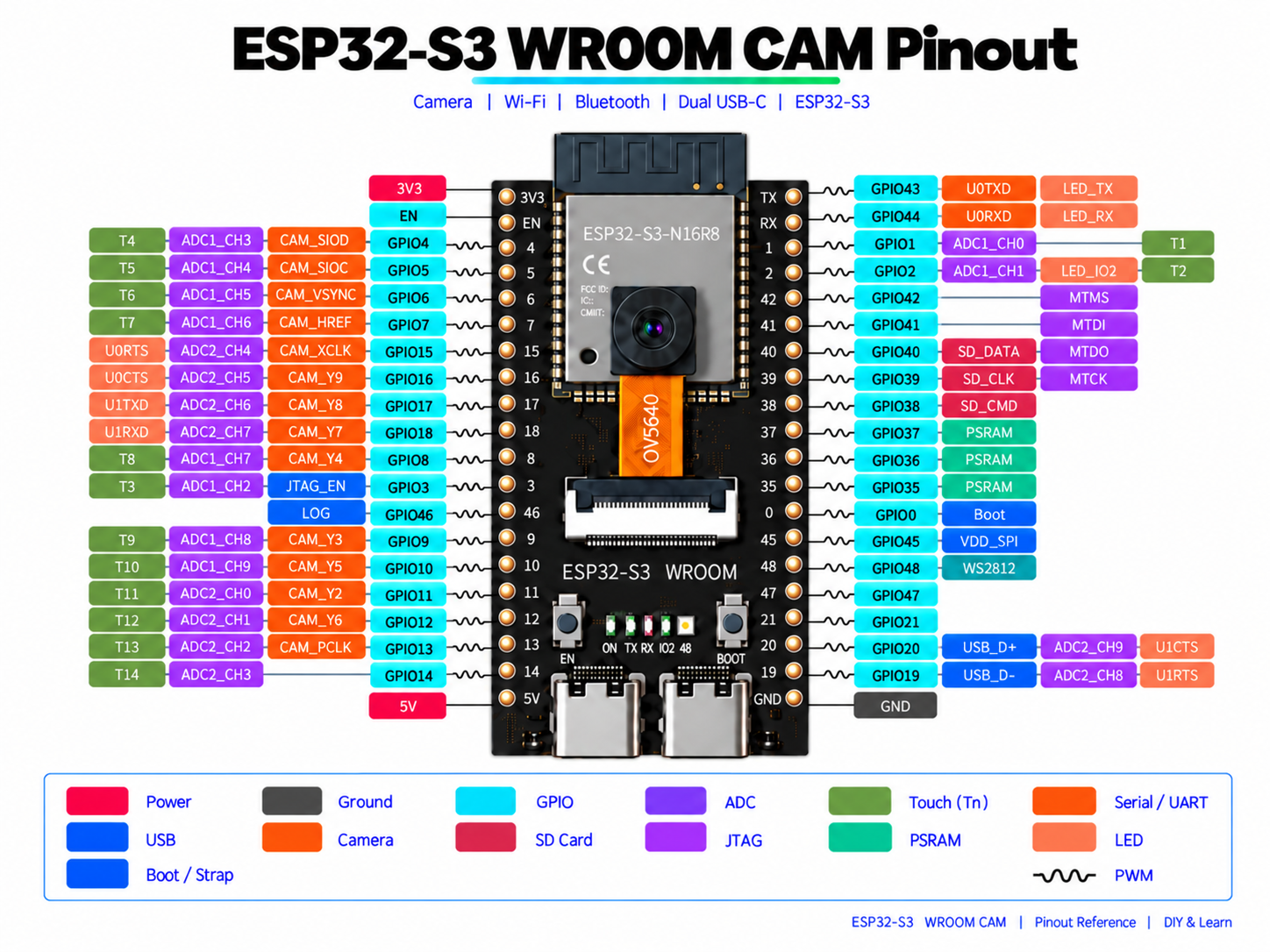
Which board this is about
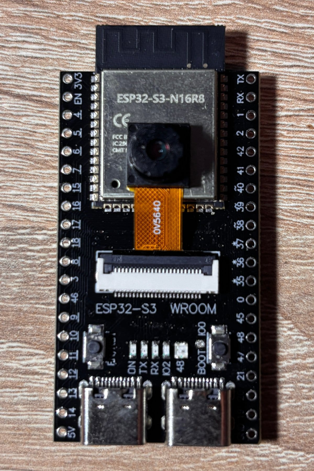
Shops sell this board under several names: ESP32-S3-CAM, ESP32-S3 WROOM CAM, ESP32-S3 CAM Development Board. The board itself modestly says ESP32-S3 WROOM, and the metal shield of the module reads ESP32-S3-N16R8. That marking is the key specification: N16 stands for 16 MB of flash, R8 for 8 MB of PSRAM. The module is an ESP32-S3-WROOM-1 with a PCB antenna.
The layout copies the Freenove ESP32-S3-WROOM CAM: the same camera position, the same pins, two buttons and two USB-C ports. Freenove ships its board with a 2 MP OV2640 camera, while the one in this article carries a 5 MP OV5640, as the marking on its ribbon cable shows. Boards like this come from several factories, and the camera module and the USB-to-UART bridge can change from batch to batch. Before hunting for a driver or somebody else’s example, it is worth checking what your own board is marked with.
Specifications
| Part | Specification | What it means in practice |
|---|---|---|
| Module | ESP32-S3-WROOM-1-N16R8, PCB antenna | A ready-made Espressif module measuring 18 × 25.5 × 3.1 mm; all 36 of its GPIOs are on the headers |
| Processor | Two Xtensa LX7 cores, up to 240 MHz, FPU | Enough for a JPEG stream, Wi-Fi and the application logic at once; it has instructions that accelerate neural networks and signal processing |
| SoC memory | 512 KB of SRAM, 384 KB of ROM | Too little internal memory for camera frames, which belong in PSRAM |
| Flash | 16 MB, Quad SPI | Room for a large application, OTA and a file system |
| PSRAM | 8 MB, Octal SPI (OPI) | Holds the camera frame buffers; the Arduino IDE needs the OPI PSRAM setting |
| Wi-Fi | 2.4 GHz, 802.11 b/g/n, up to 150 Mbit/s | MJPEG streaming, photo uploads, over-the-air updates |
| Bluetooth | Bluetooth 5 (LE), mesh, up to 2 Mbit/s and Long Range | BLE only: the ESP32-S3 has no Classic Bluetooth, so no SPP or A2DP |
| Camera | OV5640, 5 MP (2592 × 1944), 8-bit DVP bus, configured over SCCB | The sensor compresses frames to JPEG itself; the bus takes 14 GPIOs |
| Camera connector | 24-pin FPC | The camera module is replaceable with any module of the same standard |
| Memory card | microSD, SDMMC in 1-bit mode | Photos and time-lapses are written on the board itself; the slot takes GPIO38–40 |
| USB | Two USB-C ports: a USB-to-UART bridge on UART0 and the ESP32-S3’s own native USB | Flashing and logs go through the right port, USB devices and debugging through the left |
| GPIO | 36 pins on two 20-pin headers | Six are free without conditions, a few more with them |
| LEDs and buttons | ON, TX, RX and IO2 (GPIO2) LEDs plus a WS2812 RGB LED (GPIO48); EN and BOOT (GPIO0) buttons | Something to blink and something to press without any external parts |
| Power | 5 V through USB-C or the 5V pin; the 3V3 pin carries 3.3 V from the board’s regulator | The module needs a supply that can deliver at least 0.5 A |
| Logic levels | 3.3 V; the GPIOs are not 5 V tolerant | A 5 V signal needs level shifting |
| Operating temperature | −40 to +65 °C (modules with Octal PSRAM) | Lower than the 85 °C of modules without PSRAM, which matters inside a closed case |
| Development environments | Arduino IDE, PlatformIO, ESP-IDF; MicroPython with a build that includes a camera driver | Arduino is the easier quick start, ESP-IDF the better choice for a serious project |
A little arithmetic. A 5 MP frame in RGB565 takes 2592 × 1944 × 2 = 10,077,696 bytes, about 9.6 MiB. That is more than the whole 8 MB of PSRAM, which is why full resolution is only available as JPEG, compressed by the sensor itself. A UXGA frame of 1600 × 1200 in the same RGB565 takes about 3.7 MiB and does fit. In practice the camera almost always runs in JPEG: it needs less memory and is easier to send over Wi-Fi.
Two USB-C ports, and which one does what
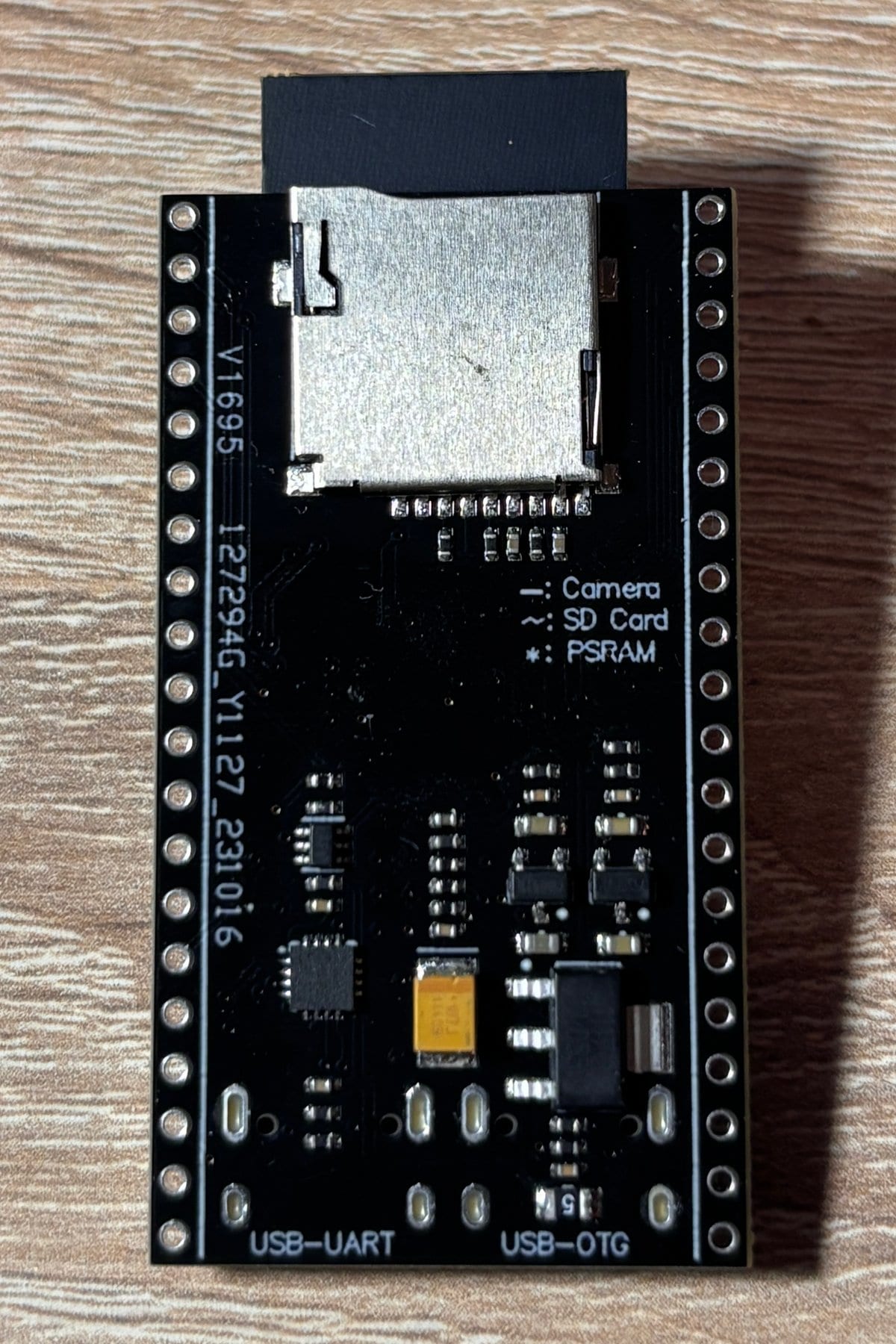
The ports are not labelled on the front: the USB-UART and USB-OTG labels are printed on the back. That sets up a classic mirror trap, because once the board is turned face up, the label on the left sits under the right-hand port. Seen from the camera side, with the antenna at the top, the picture is this:
| Port | What is behind it | Use it for |
|---|---|---|
| Left, USB-OTG | The ESP32-S3’s own native USB: GPIO19 is D−, GPIO20 is D+. The built-in USB Serial/JTAG or USB OTG | Debugging without an external adapter, and your own USB devices: keyboard, mouse, MIDI, storage, webcam |
| Right, USB-UART | A USB-to-UART bridge wired to UART0: GPIO43 is TX, GPIO44 is RX | Flashing and the Serial Monitor, the most predictable route |
Which port gets the Serial output is decided by the USB CDC On Boot setting in the Arduino IDE. With Disabled, Serial is UART0 and the messages go to the right port. With Enabled, Serial moves to the native USB, which is the left port. If the Serial Monitor stays silent, this setting and the port the cable is plugged into are the first things to check. The ROM bootloader prints to both ports by default.
The left port has a less obvious advantage too. The USB Serial/JTAG controller built into the ESP32-S3 lets you debug with breakpoints without an external adapter and without a single extra pin. That is particularly valuable here, because the default external JTAG pins (GPIO39–42) are partly taken by the memory card on this board.
The headers, pin by pin
The tables assume the board lies component side up, antenna at the top and USB ports at the bottom. The pin numbers on the silkscreen carry marks: underlined pins belong to the camera, a tilde marks the microSD pins and an asterisk the PSRAM ones. The legend is printed on the back.
Left header, top to bottom
| Pin | On this board | Free for your circuit? |
|---|---|---|
| 3V3 | 3.3 V from the board’s regulator | Not a GPIO |
| EN | Reset, the EN button; active low | No |
| GPIO4 | Camera: SIOD, SCCB data | Only without the camera |
| GPIO5 | Camera: SIOC, SCCB clock | Only without the camera |
| GPIO6 | Camera: VSYNC | Only without the camera |
| GPIO7 | Camera: HREF | Only without the camera |
| GPIO15 | Camera: XCLK | Only without the camera |
| GPIO16 | Camera: D7 (Y9) | Only without the camera |
| GPIO17 | Camera: D6 (Y8) | Only without the camera |
| GPIO18 | Camera: D5 (Y7) | Only without the camera |
| GPIO8 | Camera: D2 (Y4) | Only without the camera |
| GPIO3 | Strapping pin; ADC1, Touch3 | With care |
| GPIO46 | Boot-mode strapping pin | With care |
| GPIO9 | Camera: D1 (Y3) | Only without the camera |
| GPIO10 | Camera: D3 (Y5) | Only without the camera |
| GPIO11 | Camera: D0 (Y2) | Only without the camera |
| GPIO12 | Camera: D4 (Y6) | Only without the camera |
| GPIO13 | Camera: PCLK | Only without the camera |
| GPIO14 | Free; ADC2, Touch14 | Yes |
| 5V | 5 V rail | Not a GPIO |
Right header, top to bottom
| Pin | On this board | Free for your circuit? |
|---|---|---|
| TX (GPIO43) | UART0 TX, to the USB-to-UART bridge | Only without the right port |
| RX (GPIO44) | UART0 RX, from the USB-to-UART bridge | Only without the right port |
| GPIO1 | Free; ADC1, Touch1 | Yes, the best analogue input |
| GPIO2 | IO2 LED; ADC1, Touch2 | Mind the LED |
| GPIO42 | Free; MTMS of external JTAG | Yes |
| GPIO41 | Free; MTDI of external JTAG | Yes |
| GPIO40 | microSD: D0; MTDO of external JTAG | Only without the card |
| GPIO39 | microSD: CLK; MTCK of external JTAG | Only without the card |
| GPIO38 | microSD: CMD | Only without the card |
| GPIO37 | Octal PSRAM inside the module | Never |
| GPIO36 | Octal PSRAM inside the module | Never |
| GPIO35 | Octal PSRAM inside the module | Never |
| GPIO0 | BOOT button, strapping pin | With care |
| GPIO45 | Strapping pin: memory supply voltage | Better left alone |
| GPIO48 | WS2812-compatible RGB LED | Mind the LED |
| GPIO47 | Free | Yes |
| GPIO21 | Free | Yes |
| GPIO20 | Native USB: D+ (left port) | Only without native USB |
| GPIO19 | Native USB: D− (left port) | Only without native USB |
| GND | Ground | Not a GPIO |
Pins 35–37 do come out on the header, but they are off limits: in modules with Octal PSRAM they are wired to the memory inside, and any external signal on them interferes with it.
36 GPIOs, and how many of them are yours
Put everything together and the picture is sobering:
| Taken by | GPIO | Rule |
|---|---|---|
| Camera | 4–13, 15–18 | Taken while the camera is on |
| microSD | 38–40 | Taken while the card is mounted |
| Octal PSRAM | 35–37 | Never use them |
| Native USB | 19, 20 | Free only if you do not need the left port |
| UART0 and the USB-to-UART bridge | 43, 44 | Free only if you do not need the right port |
| On-board LEDs | 2, 48 | Usable if the LED does not get in the way |
| Strapping pins | 0, 3, 45, 46 | Only once you know their levels at reset |
| Nothing | 1, 14, 21, 41, 42, 47 | The first choice for your own circuit |
So with the camera and the memory card running, six pins are free without conditions: GPIO1, 14, 21, 41, 42 and 47. That is enough for an I²C sensor, a couple of buttons and a relay, but not for a sprawling set of peripherals. You can win back a couple more by giving up one of the USB routes: if the board only ever talks through the right port, GPIO19 and GPIO20 are released. If it only uses the left one, GPIO43 and GPIO44 are worth a try, bearing in mind that they are still wired to the USB-to-UART bridge.
Analogue inputs are trickier. On the ESP32-S3, ADC1 is GPIO1–10 and ADC2 is GPIO11–20. The camera takes almost every ADC1 pin, so with the camera running the only clean analogue input is GPIO1. GPIO2 and GPIO3 belong to ADC1 too, but the first drives an LED and the second is a strapping pin. GPIO14 belongs to ADC2, and ADC2 shares resources with Wi-Fi: while the radio is busy, a reading may be delayed or fail. For sensors in a Wi-Fi project, choose ADC1. The touch inputs Touch1–Touch14 live on GPIO1–14, but of those only GPIO1 and GPIO14 are free without conditions.
And four rules about the strapping pins that save an evening:
- GPIO0 is the BOOT button. If it is low at reset, the chip enters download mode instead of running the program. External circuitry must not pull GPIO0 to ground during start-up.
- GPIO46 is pulled down by default and selects the boot mode together with GPIO0. GPIO0 low with GPIO46 high at reset is an invalid combination.
- GPIO45 sets the memory supply voltage: low at reset means 3.3 V, high means 1.8 V. This module’s flash and PSRAM are 3.3 V parts, so GPIO45 must not be high during reset. It is pulled down by default, and that is how it should stay.
- GPIO3 selects the JTAG signal source, but only if the corresponding eFuse bit has been burned; on a module with factory settings its level is ignored. Espressif still lists it as a strapping pin, so it is better not to make it the first home for a button.
The camera: an OV5640 on the right pin map
The camera sits on a parallel DVP bus: eight data lines, three sync lines, the XCLK clock and a pair of SCCB lines to configure the sensor, 14 GPIOs in all. The PWDN and RESET pins are not connected on this board, so the configuration sets them to -1.
The main trap is somebody else’s pin map. The most popular examples online are written for the AI-Thinker ESP32-CAM, and on an ESP32-S3 its GPIO numbers point, among other things, at pins 26–32, which the S3 gives to its internal memory, and at 22–25, which the S3 does not have at all. The good news is that this board’s wiring matches Espressif’s ESP32-S3-EYE exactly, and the Arduino core already describes that board.
In the CameraWebServer example (File → Examples → ESP32 → Camera), the model is chosen in board_config.h. The default there is CAMERA_MODEL_ESP_EYE, which is a different board built on the original ESP32. Comment that line out and uncomment CAMERA_MODEL_ESP32S3_EYE. This is how that model’s pins look in camera_pins.h, exactly as on our board:
#define PWDN_GPIO_NUM  -1
#define RESET_GPIO_NUM -1
#define XCLK_GPIO_NUM  15
#define SIOD_GPIO_NUM  4
#define SIOC_GPIO_NUM  5

#define Y2_GPIO_NUM 11
#define Y3_GPIO_NUM 9
#define Y4_GPIO_NUM 8
#define Y5_GPIO_NUM 10
#define Y6_GPIO_NUM 12
#define Y7_GPIO_NUM 18
#define Y8_GPIO_NUM 17
#define Y9_GPIO_NUM 16

#define VSYNC_GPIO_NUM 6
#define HREF_GPIO_NUM  7
#define PCLK_GPIO_NUM  13
For this model the example flips the picture vertically on its own with set_vflip. If the image comes out upside down, toggling V-Flip in the web interface is enough; the resolution is raised there too, since the stream starts in QVGA. A missing PSRAM, on the other hand, the example survives silently: if psramFound() returns false, the frame size is capped at SVGA and the buffer moves to internal memory. The camera still works, but far from at full strength.
If the stream stays black
The OV5640 has a known quirk on this board. Owners have reported that the example initialises the camera without errors, an OV2640 works on the same board, and the OV5640 delivers a black frame. According to their reports, changing the XCLK clock helps: 24 MHz or 12 MHz instead of the default 20 MHz. In setup() that is a single line, xclk_freq_hz; the other fields show what it is usually combined with:
camera_config_t config;
// ... pins as in camera_pins.h ...
config.xclk_freq_hz = 24000000;   // 20 MHz gave black frames on some OV5640 boards; 12 MHz is the other reported fix
config.pixel_format = PIXFORMAT_JPEG;
config.frame_size   = FRAMESIZE_UXGA;
config.jpeg_quality = 10;
config.fb_location  = CAMERA_FB_IN_PSRAM;
config.fb_count     = 2;
config.grab_mode    = CAMERA_GRAB_LATEST;
If that does not help, check that the ribbon cable is fully seated and its latch closed, and that the board is not overheating: the same discussions advise against keeping it in a closed case without ventilation while the camera runs. The sensor’s full resolution, FRAMESIZE_5MP at 2592 × 1944, is only available in JPEG.
Arduino IDE settings
The board needs no separate package: the standard ESP32S3 Dev Module profile from arduino-esp32 does the job. What matters most is describing the memory correctly, because that decides whether the program sees the PSRAM at all.
| Setting | Value | Why |
|---|---|---|
| Board | ESP32S3 Dev Module | The generic ESP32-S3 profile |
| Flash Size | 16MB (128Mb) | The real flash size of the N16R8 module |
| Flash Mode | QIO 80MHz | The flash here is Quad SPI; OPI 80MHz is meant for modules with Octal flash |
| PSRAM | OPI PSRAM | The PSRAM is Octal SPI; with QSPI PSRAM or Disabled the program will not find it |
| Partition Scheme | 16M Flash (3MB APP/9.9MB FATFS) | CameraWebServer needs at least 3 MB for the application; the rest goes to files |
| USB CDC On Boot | Disabled to work through the right port, Enabled through the left | Decides which port Serial uses |
| USB Mode | Hardware CDC and JTAG | The built-in USB Serial/JTAG; USB-OTG (TinyUSB) is for your own USB devices |
| Upload Mode | UART0 / Hardware CDC | Flashing through either port |
If flashing stops working, for example because the program reconfigured the native USB or fell into a reboot loop, put the board into the bootloader by hand: hold BOOT, briefly press EN, release BOOT and upload again. The right port may need a driver for the USB-to-UART bridge on your computer. The original Freenove board uses a CH343, clones sometimes carry other chips, so go by what the device manager actually reports. Current operating systems recognise the left port as a serial port without a separate driver.
microSD, LEDs and buttons
The microSD slot is wired for SDMMC in 1-bit mode: CMD on GPIO38, CLK on GPIO39, D0 on GPIO40. That is slower than 4-bit mode but saves three pins. Two of the three lines coincide with the default external JTAG pins (MTCK and MTDO), so the card and an external debugger get in each other’s way; with a card inserted, debugging through the left USB port is the easier route.
There are five LEDs. ON shows power, TX and RX flicker with traffic through the USB-to-UART bridge, IO2 is a user LED on GPIO2, and 48 is a WS2812-compatible addressable RGB LED on GPIO48. In the ESP32S3 Dev Module profile, both LED_BUILTIN and RGB_BUILTIN point at that RGB LED, so the stock Blink sketch lights it white. Its colour is set with rgbLedWrite(); the older neopixelWrite() is deprecated.
EN restarts the module, and BOOT is wired to GPIO0 for entering the bootloader by hand. Once the program is running, BOOT can be read like any other button. A quick self-test of the board mounts the card and reports the result in colour:
#include "SD_MMC.h"

void setup() {
  Serial.begin(115200);

  // One-bit SDMMC: CLK, CMD, D0
  SD_MMC.setPins(39, 38, 40);

  if (SD_MMC.begin("/sdcard", true)) {
    Serial.printf("microSD: %llu MB\n", SD_MMC.cardSize() / (1024 * 1024));
    rgbLedWrite(RGB_BUILTIN, 0, 32, 0);   // green: card mounted
  } else {
    Serial.println("microSD: mount failed");
    rgbLedWrite(RGB_BUILTIN, 32, 0, 0);   // red: no card
  }
}

void loop() {}
Power and heat
The board takes power through either USB-C port or the 5V pin. The 3V3 pin is the output of the board’s regulator and can feed low-power 3.3 V sensors. The GPIOs work at 3.3 V only: a 5 V signal on an input can damage the module, whose absolute maximum supply voltage is 3.6 V.
The camera, Wi-Fi transmission and card writes all cause current peaks. The module datasheet asks for a supply that can deliver at least 0.5 A, and a weak USB port or a long, thin cable easily falls short. The symptoms are easy to recognise: the board resets the moment the stream starts, and the log shows a message from the brownout detector. The cure is a short, decent cable and a proper 5 V power supply.
The second limit is less obvious: temperature. Modules with Octal PSRAM, the N16R8 included, are rated for an ambient temperature of up to 65 °C, whereas the variants without PSRAM go up to 85 °C. Espressif notes that enabling PSRAM error correction (ECC) raises the limit to 85 °C at the cost of 1/16 of the memory. The camera and the radio keep warming the board, so inside a closed case in the sun that margin disappears quickly; plan ventilation holes from the start.
What to build on it: three telling cases
1. A camera for the 3D printer
Checking on a print from another room, and collecting a time-lapse along the way, is the most natural job for a board like this. Prusa-Firmware-ESP32-Cam, the firmware that connects a camera to the Prusa Connect service, has a dedicated page for the Freenove ESP32-S3-WROOM. The camera modules tested there are OV2640s, so OV5640 compatibility is something to find out for yourself, but the board layout is the same.
2. A time-lapse recorder with its own card
The microSD slot turns the board into a standalone recorder: wake on a timer, take a JPEG, write it to the card and go back to sleep. That is how people film plants growing, a building site across the street or a slow process in the workshop. The board is not optimised for battery power, though: the ON LED is always lit, and the camera’s PWDN pin is not connected, so the sensor cannot be powered down in hardware, only put into its software standby over SCCB. Sleep current will be noticeably higher than for a bare module; that does not matter for a mains-powered time-lapse, but it does on batteries.
3. A USB webcam and vision on the device itself
Native USB lets the ESP32-S3 present itself to a computer as a webcam. Espressif’s esp-iot-solution has a usb_webcam example: the board becomes a UVC device streaming MJPEG, and the example’s list of modes includes 1280 × 720 at 15 frames per second. By default it builds for the ESP32-S3-EYE, which means the same pin map as this board. The other direction is processing frames on the device itself: Espressif’s ESP-WHO framework targets the ESP32-S3 and can, for instance, detect faces with no cloud involved.
Strengths and weaknesses
| Strengths | Weaknesses |
|---|---|
| Two USB-C ports: flashing without an adapter, plus native USB | The ports are labelled only on the back and easy to mix up |
| 16 MB of flash and 8 MB of Octal PSRAM | Modules with Octal PSRAM are rated only up to 65 °C |
| A replaceable 5 MP camera | The OV5640 can give a black frame until the XCLK frequency is tuned |
| A microSD slot right on the board | The card takes three pins and clashes with external JTAG |
| All 36 module GPIOs on the headers, with the taken ones marked on the silkscreen | Only six pins are free without conditions |
| The pin map matches the ESP32-S3-EYE, so ready-made examples fit with a minimal change | Not optimised for battery devices: PWDN is not connected and the power LED is always on |
| A user LED and an RGB LED on the board | Batches differ in the camera and the USB-to-UART bridge |
Bottom line
The ESP32-S3-CAM N16R8 is an ESP32-CAM with nearly all of its teething troubles cured: proper USB, plenty of memory, a replaceable 5 MP camera and honest marking of the taken pins right on the board. For a workshop camera, a time-lapse, keeping an eye on a 3D printer or experimenting with machine vision, it is a very convenient base.
The price of that convenience is a tight fit. The camera and the memory card eat almost every pin, the PSRAM has to be enabled correctly, and the OV5640 may need its clock tuned. Before the first flash it pays to run through a short list:
- ESP32S3 Dev Module profile: 16 MB flash, QIO 80MHz, PSRAM set to OPI PSRAM.
- Pin map:
CAMERA_MODEL_ESP32S3_EYE, not AI-Thinker. - Frame buffers in PSRAM, format JPEG.
- microSD as 1-bit SDMMC on GPIO38, 39 and 40.
- The cable in the port that matches the USB CDC On Boot setting.
- New connections on GPIO1, 14, 21, 41, 42 and 47 first.
- GPIO0, 3, 45 and 46 kept free of circuits that change their level at reset.
Everything above in a single file: a reference to the board’s pins and hardware limits. Keep it next to your sketch, or hand it to a coding agent so it does not invent a pinout.



Placed here so the comments block has something to render. A comment long enough to wrap is worth more than a one-word one, because the indentation of a reply only shows up against a real paragraph.