3.5-Inch TFT LCD Shield: a 480 × 320 Screen on a Fast 8-Bit Bus
Most small hobby displays talk SPI: one clock line, one data line, and every byte squeezed through a bit at a time. The red 3.5-inch shield in this article works differently. Turn it over and instead of MOSI and SCK you find eight data lines, LCD_D0 to LCD_D7, so every clock tick carries a whole byte. Add 480 × 320 pixels, a resistive touch film and a microSD slot, and you have one of the largest screens that plug straight into an Arduino Uno without a single wire.
It is worth a closer look even if you have never owned an Uno. We wired it to an ESP32-S3 with a hardware 8080 peripheral, ran the bus at 20 MHz and played full-screen 480 × 320 video from a microSD card at 25 frames per second; you can watch it in the section on speed. Below: what is on the board, how its bus works and how to program it, where the speed comes from and where it gets lost, and what to build with it, from a weather station to a photo frame and a wall panel.
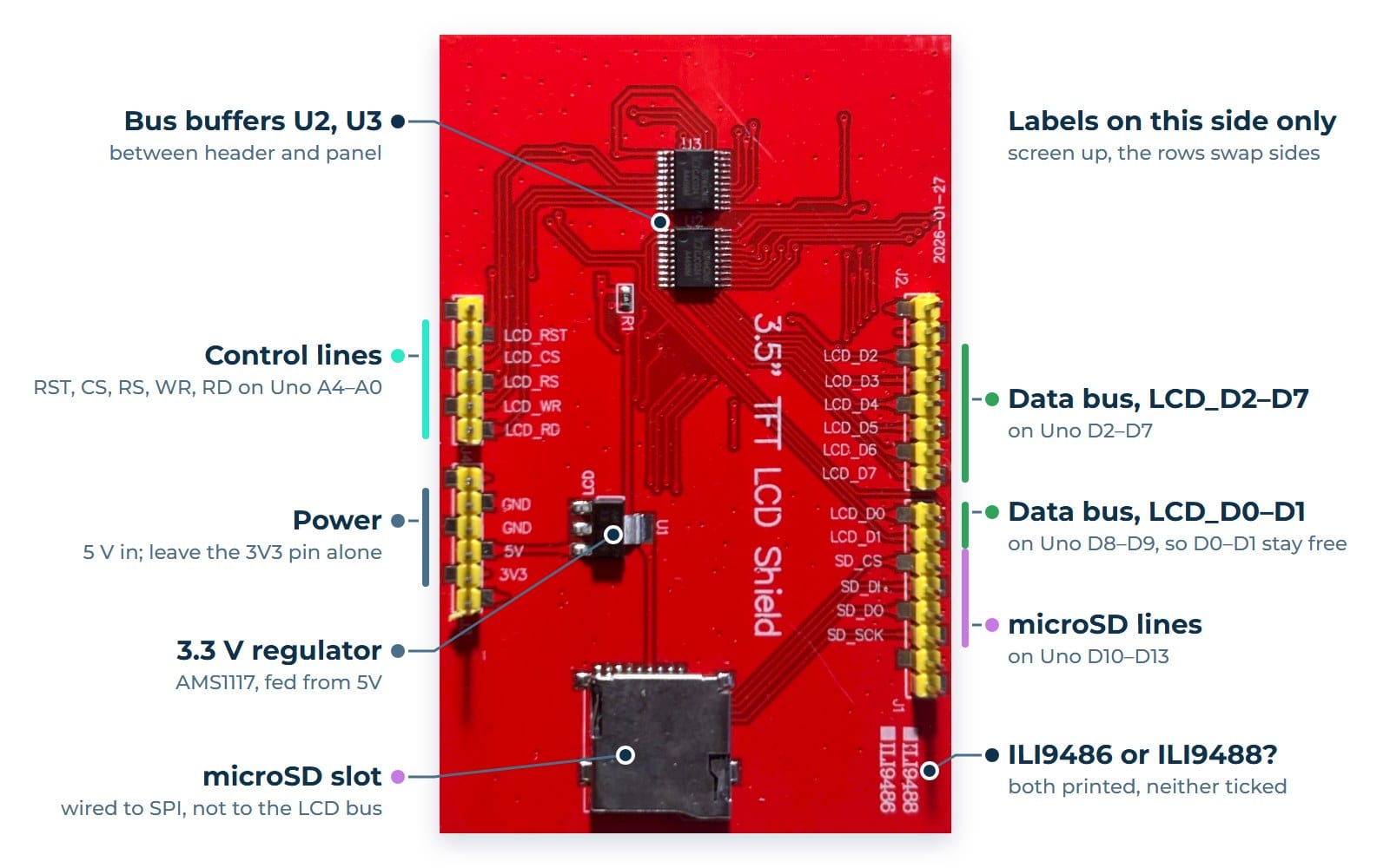
Which board this is about
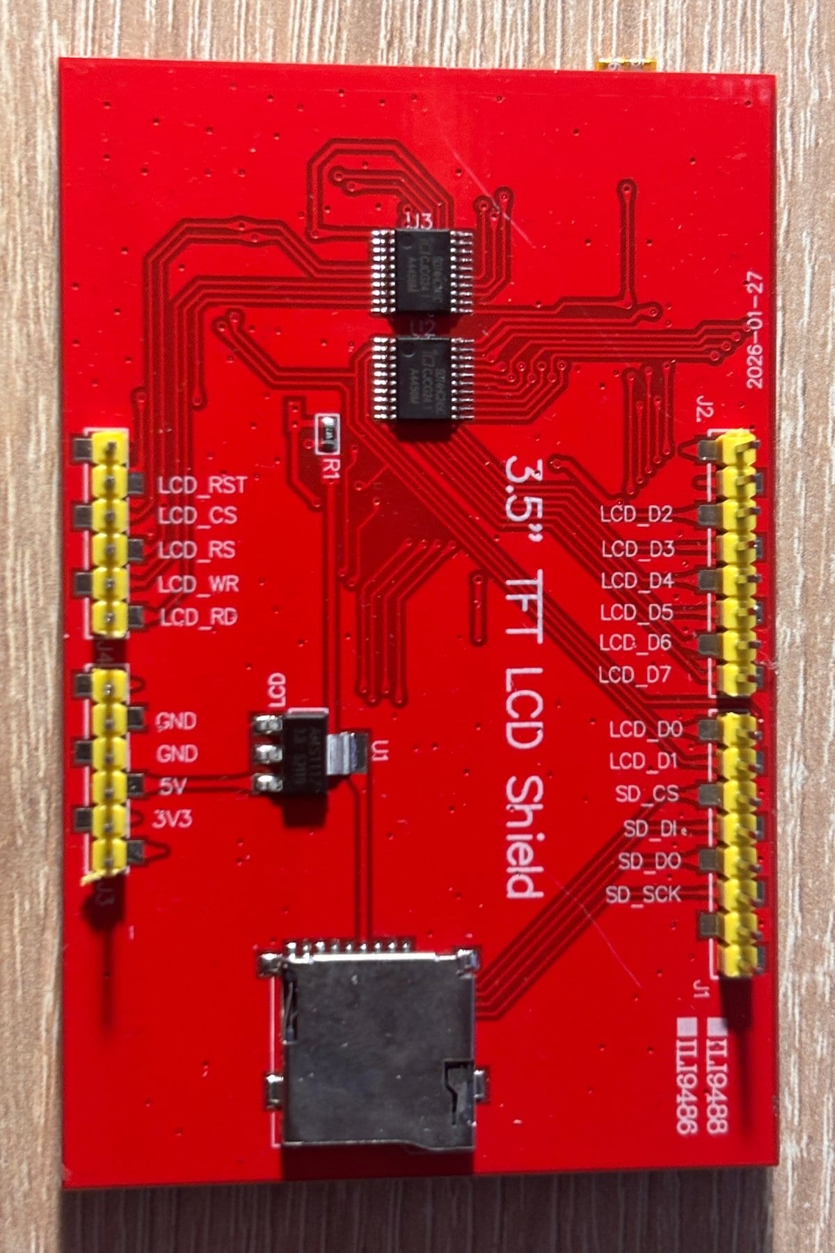
Shops sell it as a “3.5 inch TFT LCD Shield for Arduino UNO/Mega”, and several factories make boards that look alike but differ in their parts. The one here has a red PCB with a 3.5″ TFT LCD Shield silkscreen and a date code of 2026-01-27. Its most telling detail is in a corner: two boxes printed with ILI9488 and ILI9486, and neither of them ticked. The controller itself is chip-on-glass, hidden under the panel, so the board does not tell you which of the two it carries.
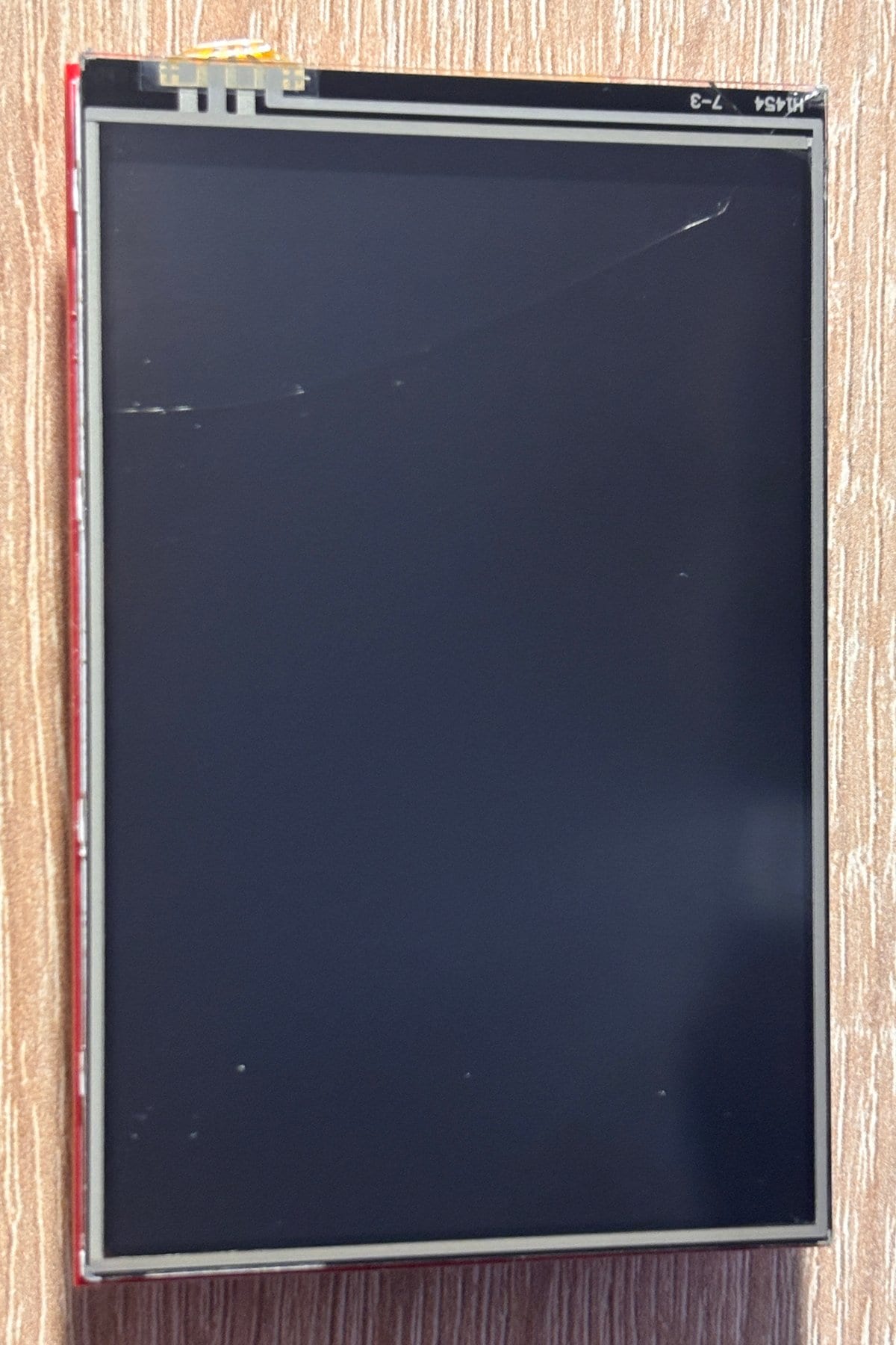
Ours shows a correct, stable picture with the ILI9488 initialisation sequence, so it is most likely an ILI9488. That is a working hypothesis rather than an identification: both controllers share the core commands, and the wrong sequence often produces a picture too, just with poor contrast or flicker. Another board from the same shop may carry the other chip. The front holds a 4-wire resistive touch film, with a four-contact flex along the top edge and the glass marked H1454 7-3. There is no touch controller chip anywhere on the board.
Specifications
| Part | What it is | In practice |
|---|---|---|
| Panel | 3.5-inch TFT, 320 × 480 native, 480 × 320 in landscape | 153,600 pixels: room for a graph with labels, a photo or a video frame |
| Controller | ILI9486 or ILI9488, chip-on-glass; ours behaves as an ILI9488 | The two need different init sequences; the wrong one still shows a picture, only a worse one |
| Interface | Intel 8080-style parallel bus: eight data lines plus CS, RS, WR, RD and RST | 13 host pins; one byte per write strobe |
| Colour | RGB666, 262K colours, 3 bytes per pixel: verified. RGB565, 65K colours, 2 bytes: expected to work | Two bytes per pixel would cut the traffic by a third |
| Write clock | 20 MHz verified over jumper wires; the ILI9488 datasheet allows up to 25 MHz | A full frame in 23 ms at three bytes per pixel |
| Touch | 4-wire resistive film, no controller chip | The host measures it with its own ADC, through pins shared with the display |
| Storage | microSD socket on SPI, Uno pins D10–D13 | Photos, fonts and video on the board itself |
| Power | 5 V into the 5V pin; an AMS1117 3.3 V regulator on board | One supply for the panel, the logic and the backlight |
| Logic levels | 3.3 V host logic verified; the 5 V logic of an Uno is what the shield was made for | Works with an ESP32, RP2040 or STM32 as well as with AVR boards |
| Backlight | Always on; no control pin | No dimming in software; to save power, switch the 5 V off |
| Form factor | Arduino Uno R3 shield, 28 header pins | Plugs into an Uno or a Mega; any other host needs jumper wires |
Some arithmetic first. A frame is 480 × 320 = 153,600 pixels: 460,800 bytes at three bytes per pixel, 307,200 at two. The 8-bit bus moves one byte per write strobe, so at 20 MHz it carries 20 million bytes a second, and a full frame takes 23 ms, or 15.4 ms at two bytes per pixel. SPI moves one bit per clock. At 20 MHz, the limit the ILI9488 datasheet sets for its SPI interface, the same frame takes 184 ms, and even overclocked to 40 MHz it takes 92 ms.
The pins: wire by the label
The shield follows the Arduino Uno layout, but the labels matter more than the Uno numbers. The data byte is split in a way that surprises people: LCD_D2 to LCD_D7 sit on Uno pins D2 to D7, while LCD_D0 and LCD_D1 moved to D8 and D9, so that D0 and D1 stay free for the Uno’s serial port.
| Uno pin | Label | What it does |
|---|---|---|
| A0 | LCD_RD | Read strobe, active low; keep it high |
| A1 | LCD_WR | Write strobe, active low; the panel latches the data on its rising edge |
| A2 | LCD_RS | Register select: 0 for a command, 1 for data; D/C in other libraries |
| A3 | LCD_CS | Chip select, active low |
| A4 | LCD_RST | Reset, active low |
| D2–D7 | LCD_D2–D7 | Data bits 2 to 7 |
| D8, D9 | LCD_D0, LCD_D1 | Data bits 0 and 1 |
| D10 | SD_CS | microSD chip select |
| D11 | SD_DI | microSD data in, MOSI |
| D12 | SD_DO | microSD data out, MISO |
| D13 | SD_SCK | microSD clock |
| 5V, GND | 5V, GND | Power for the whole board |
| 3.3V | 3V3 | Where it connects is unknown; do not use it as a supply |
Two things catch people out. The labels are printed only on the back, so with the screen facing you the left and right rows swap sides: wire strictly by label, never by position. And on an Uno the shield takes nearly everything. What is left is D0 and D1, which are the serial port, the unlabelled A5, and the SPI pins shared with the memory card. I²C is gone, because A4, the Uno’s SDA, is LCD_RST. A weather station with a couple of sensors therefore wants a Mega, or better, a 32-bit board on jumper wires.
How the 8-bit bus talks
The bus is the Intel 8080 style, which the ILI9488 datasheet calls DBI Type B. It has no clock in the SPI sense: the host puts a byte on D0–D7 and pulses WR, and the panel takes the byte on the rising edge. RS says what the byte is, 0 for a command and 1 for a parameter or pixel data. CS frames the transaction, RST resets the controller, and RD is the read strobe.
| Signal | At rest | Role |
|---|---|---|
| CS | High | Low while the host talks to the panel |
| RS | Either | 0 for a command byte, 1 for a parameter or pixel data |
| WR | High | One short low pulse per byte; the panel latches D0–D7 on the rising edge |
| RD | High | Must never float; held high unless reading |
| RST | High | Low resets the controller |
| D0–D7 | — | Driven by the host; the panel drives them only while RD is low |
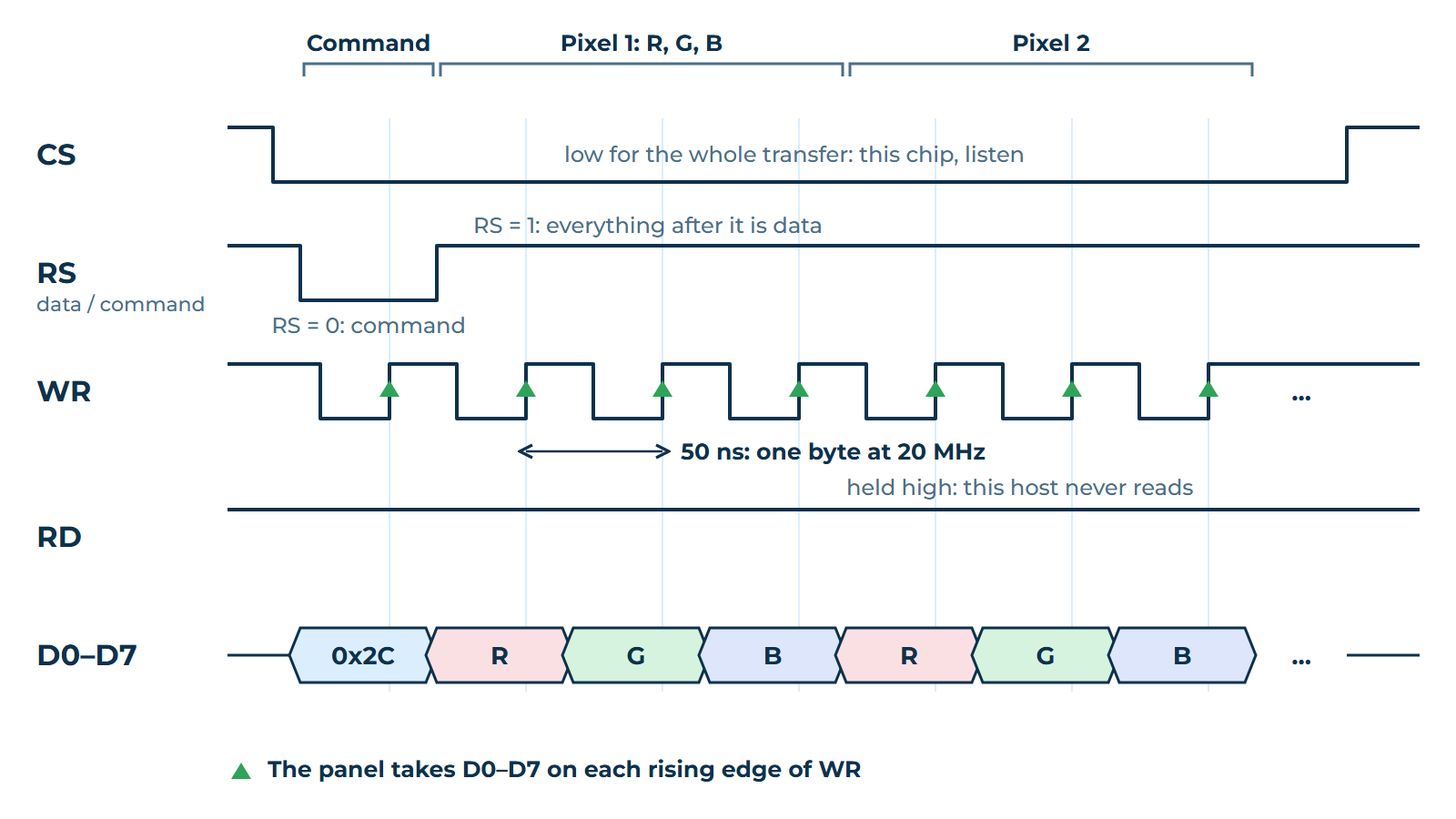
That is the whole protocol. A command goes out with RS low, and its parameters follow with RS high. Pixels are no different from parameters: after the RAMWR command, 0x2C, every byte sent with RS high lands in the panel’s memory, and the stream can run for as long as the host likes.
Drawing: a window and a stream
The controller keeps the whole picture in its own memory and refreshes the glass from it by itself, so the host sends only what changes. To draw, it opens a window: CASET, 0x2A, sets the first and last column, PASET, 0x2B, the first and last row. After RAMWR the pixels fill that window left to right and top to bottom, with no coordinates in between. Two bus functions, one for a command byte and one for data bytes, are all a port needs:
static void set_window(uint16_t x0, uint16_t y0, uint16_t x1, uint16_t y1) {
    uint8_t ca[4] = { (uint8_t)(x0 >> 8), (uint8_t)x0,
                      (uint8_t)(x1 >> 8), (uint8_t)x1 };
    uint8_t pa[4] = { (uint8_t)(y0 >> 8), (uint8_t)y0,
                      (uint8_t)(y1 >> 8), (uint8_t)y1 };
    lcd_write_cmd(0x2A); lcd_write_data(ca, 4);   // CASET: columns
    lcd_write_cmd(0x2B); lcd_write_data(pa, 4);   // PASET: rows
}

// A solid rectangle in RGB666: 3 bytes per pixel, one window
static void fill_rect(uint16_t x, uint16_t y, uint16_t w, uint16_t h,
                      uint8_t r, uint8_t g, uint8_t b) {
    const uint8_t px[3] = { r, g, b };
    set_window(x, y, x + w - 1, y + h - 1);
    lcd_write_cmd(0x2C);                           // RAMWR
    for (uint32_t i = 0; i < (uint32_t)w * h; i++) {
        lcd_write_data(px, 3);
    }
}
The window is where speed is won or lost. Stream as many pixels as possible inside one window: a window per pixel costs eleven bytes of commands and coordinates for every three bytes of colour.
Pixel formats and orientation
Two registers settle how the picture looks. COLMOD, 0x3A, sets the pixel format. 0x66 is RGB666, three bytes per pixel with the colour in the top six bits of each byte, and that is what runs on our board. 0x55 is RGB565, two bytes per pixel: both datasheets list it for the parallel bus and the popular libraries use it there, but we have not tested it on this unit yet. If the bytes you send per pixel don’t match COLMOD, solid fills come out as fine stripes of wrong colours that cover only part of the window.
MADCTL, 0x36, sets the orientation and the colour order. On this board 0x28 gives a correct, unmirrored 480 × 320 landscape picture, and the BGR bit it includes is why colours go out in plain R, G, B order. Swapped red and blue are fixed with that bit, mirroring with the MX and MY bits and swapped axes with MV, never in the application code.
| MADCTL | Picture | On this board |
|---|---|---|
| 0x48 | Portrait, 320 × 480 | Standard value, not tested |
| 0x28 | Landscape, 480 × 320 | Verified |
| 0x88 | Portrait, turned over | Not tested |
| 0xE8 | Landscape, turned over | Not tested |
ILI9486 or ILI9488?
In theory the controller reports its identity: command 0xD3 returns a dummy byte followed by 0x00, 0x94 and 0x86 or 0x88. In practice many shields of this family are write-only. Their bus buffers are wired one way, from the header to the panel, so nothing the panel says ever reaches the host. The popular MCUFRIEND_kbv library then reads its own command byte back and reports the ID as 0xD3D3; its test sketch marks that case as a write-only shield.
On such a board the controller is identified by eye. Initialise it with the ILI9488 sequence and draw solid fills, grey and colour gradients and a one-pixel grid, then repeat with the ILI9486 sequence, and keep the one that gives smooth gradients, good contrast and no flicker. We have not tried to read the ID on ours. With the ILI9488 sequence its picture is right, so that is the sequence below.
The ILI9488 initialisation sequence that works on this board
RST: high 50 ms, low 50 ms, high 150 ms             ; hardware reset
0x01                                                ; SWRESET, wait 120 ms
0x28                                                ; DISPOFF
0xE0: 00 03 09 08 16 0A 3F 78 4C 09 0A 08 16 1A 0F  ; positive gamma
0xE1: 00 16 19 03 0F 05 32 45 46 04 0E 0D 35 37 0F  ; negative gamma
0xC0: 17 15                                         ; power control 1
0xC1: 41                                            ; power control 2
0xC5: 00 12 80                                      ; VCOM control
0x36: 48                                            ; MADCTL: portrait, BGR
0x3A: 66                                            ; COLMOD: RGB666
0xB0: 00                                            ; interface mode
0xB1: A0                                            ; frame rate
0xB4: 02                                            ; inversion control
0xB6: 02 02 3B                                      ; display function
0xB7: C6                                            ; entry mode
0xF7: A9 51 2C 82                                   ; adjust control 3
0x11                                                ; SLPOUT, wait 120 ms
0x29                                                ; DISPON, wait 25 ms
0x36: 28                                            ; MADCTL: landscape
Each line is a command followed by its parameter bytes. With COLMOD set to 0x55 instead of 0x66 the panel would expect RGB565, which we have not tested yet. The register values match TFT_eSPI’s ILI9488 driver, except that the library selects 0x55 for parallel buses. The ILI9486 alternative is in the programming guide at the end of the article.
Where the speed comes from
SPI moves one bit per clock. The 8-bit bus moves a byte. At the same clock that is eight times the data, and it is the whole reason this old-fashioned interface is still around: it needs thirteen pins instead of four or five, but it fills a large screen in a fraction of the time.
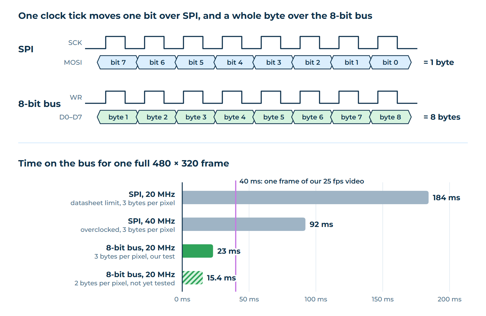
SPI is also handicapped on this particular family of controllers. Over SPI the ILI9486 takes full colour only in 18-bit form, and although the ILI9488 datasheet lists 16-bit colour for its 4-wire SPI mode, in practice these chips are driven with three bytes per pixel, which is exactly what the popular libraries do. The same datasheet caps the ILI9488’s SPI write clock at 20 MHz. Its parallel bus is allowed a write cycle of 40 ns, which is 25 MHz, so our 20 MHz sits inside the specification. The ILI9486 is slower: its datasheet asks for at least 66 ns per write, about 15 MHz. If your board turns out to carry that chip, start below that figure.
The bus, though, is only as fast as the host that drives it. Toggling thirteen pins one by one with digitalWrite() turns the fastest interface on the board into one of the slowest. Writing whole port registers is much better, and a hardware peripheral with DMA is best of all: the LCD_CAM of an ESP32-S3, the PIO of an RP2040 or the FSMC of an STM32 send the bytes on their own while the processor prepares the next ones.
Our test: 25 fps video from a microSD card
The host was the ESP32-S3-CAM N16R8 from our previous article, wired to the shield with jumper wires. On that board the 13 bus lines took GPIOs that the camera normally uses, so the camera sat this test out. The bus ran through ESP-IDF’s esp_lcd i80 driver on the S3’s LCD_CAM peripheral at a 20 MHz write clock, with the ILI9488 sequence, RGB666 and landscape orientation. Two DMA buffers of 30,720 bytes, enough for 10,240 pixels each, take turns: while one is on its way to the panel, the other is being filled.
The player splits the work between the two cores. One reads MJPEG files from the board’s own microSD card; the other decodes each frame with the JPEGDEC library and pushes the decoded blocks straight into the DMA buffers, converting RGB565 to RGB666 on the way. The result is steady full-screen 480 × 320 video at 25 frames per second. Of the 40 ms each frame may take, the bus needs 23. Over SPI at an overclocked 40 MHz the same frame would need 92 ms on the bus alone, so 25 fps would be out of reach before a single pixel was decoded.
Setting the bus up takes two structures. This is how our driver does it. RD is not part of it at all: esp_lcd has no read path, so an ordinary GPIO simply holds RD high.
esp_lcd_i80_bus_config_t bus_config = {};
bus_config.dc_gpio_num = PIN_LCD_RS;
bus_config.wr_gpio_num = PIN_LCD_WR;
bus_config.clk_src = LCD_CLK_SRC_PLL160M;
bus_config.data_gpio_nums[0] = PIN_LCD_D0;     // likewise [1] to [7]
bus_config.bus_width = 8;
// One DMA chunk: 32 lines of 320 pixels in RGB666
bus_config.max_transfer_bytes = 320 * 32 * 3;
esp_lcd_new_i80_bus(&bus_config, &i80_bus);

esp_lcd_panel_io_i80_config_t io_config = {};
io_config.cs_gpio_num = PIN_LCD_CS;
io_config.pclk_hz = 20 * 1000 * 1000;          // 20 MHz write clock
io_config.trans_queue_depth = 10;
io_config.lcd_cmd_bits = 8;
io_config.lcd_param_bits = 8;
io_config.dc_levels.dc_cmd_level = 0;          // RS low: command
io_config.dc_levels.dc_data_level = 1;         // RS high: data
esp_lcd_new_panel_io_i80(i80_bus, &io_config, &io_handle);
From there esp_lcd_panel_io_tx_param() sends commands with their parameters, and esp_lcd_panel_io_tx_color() queues pixel data for DMA and returns at once. That is also the trap: a buffer must not be refilled before its transfer has finished, or blocks of the picture come out corrupted.
Two limits remain. The controller refreshes the glass from its memory about 60 times a second with the usual settings, and the shield does not bring out the tearing-effect signal that would let the host time its writes to that refresh, so fast motion can show a tear line. And a full frame buffer, 460,800 bytes in RGB666, fits only into external PSRAM, which is why our driver streams small chunks from internal memory instead.
Which host, which library
The shield was designed for the Uno, but the Uno is the slowest home it can have. The table sums up the usual routes; the programming guide at the end has the pin constraints for each.
| Host | Route | Watch out for |
|---|---|---|
| Arduino Uno | Plugs in. MCUFRIEND_kbv with Adafruit_GFX, plus Adafruit TouchScreen for the film | 2 KB of SRAM: no frame buffer, images are streamed from the card. The data byte is split across two ports, which costs time |
| Arduino Mega | Plugs in. MCUFRIEND_kbv | The Uno pins land on scattered Mega ports, a slower mapping than on the Uno; plenty of memory and pins to spare |
| ESP32 | esp_lcd i80 through I2S, LovyanGFX, TFT_eSPI | GPIO34–39 are input-only. Uno-format boards such as the Wemos D1 R32 put LCD_RS, LCD_CS and LCD_RST on them, so those three need rewiring |
| ESP32-S3 | esp_lcd i80 on LCD_CAM with DMA, as in our test; LovyanGFX and Arduino_GFX use LCD_CAM too | Any GPIO can carry any signal. TFT_eSPI works as well, but on the S3 it toggles GPIO registers without DMA |
| RP2040 | TFT_eSPI with PIO and DMA | D0–D7 must sit on consecutive GPIOs |
| STM32 | FSMC or FMC in 8080 mode where the package allows; port writes otherwise | FSMC pins are fixed for each package |
Whatever the host, plan the pins with touch in mind: the film shares lines with the display, and its analogue ends need ADC-capable pins. More on that below.
On an Uno the quickest start is MCUFRIEND_kbv. We have not run this sketch on an Uno ourselves: it is the library’s standard route, with one addition for write-only boards.
#include <Adafruit_GFX.h>
#include <MCUFRIEND_kbv.h>

MCUFRIEND_kbv tft;

void setup() {
  Serial.begin(9600);
  uint16_t id = tft.readID();
  Serial.print(F("ID = 0x"));
  Serial.println(id, HEX);
  // A write-only shield reads back 0xD3D3: name the controller yourself
  if (id == 0xD3D3) id = 0x9488;
  tft.begin(id);
  tft.setRotation(1);              // landscape, 480 × 320
  tft.fillScreen(0x0000);          // black
  tft.setTextColor(0x07E0);        // green
  tft.setTextSize(3);
  tft.setCursor(24, 24);
  tft.print(F("Hello, 480 x 320"));
}

void loop() {}
Touch without a touch controller
The touch film is the classic 4-wire resistive kind: two resistive layers that meet where you press. There is no XPT2046 or similar chip to read it. Instead, its four electrodes are wired to lines the display already uses, and the host measures them with its own ADC. It drives a voltage across one layer and reads where the other layer taps into it, then swaps the roles for the other axis.
Which lines carry the electrodes varies from board to board, and on ours we have not traced them yet. On shields of this family the analogue ends usually sit on LCD_WR, LCD_RS or LCD_CS, and the digital ends on data lines such as LCD_D6 and LCD_D7. A multimeter finds them in a minute: with the board unpowered, two pairs between the control lines and the data lines read a few hundred ohms, around 300 for one layer and 500 for the other.
Reading the touch then means borrowing those pins from the display. Wait until the bus is idle, keep the control line that is not an electrode inactive so the panel ignores the noise, take several samples, and put every pin back into its display role before the next transfer. Skip that last step and you get random pixels and a frozen screen. With a hardware peripheral such as LCD_CAM it is harder still, because the pins have to be released from the peripheral and reattached, so decide how you will read the touch before you fix the pin map. The film also prefers big targets: buttons the size of a fingertip suit it far better than a phone-style interface.
microSD, power and backlight
The microSD socket has its own SPI lines, SD_CS, SD_DI, SD_DO and SD_SCK on Uno pins D10 to D13, electrically separate from the display bus. On any other host it can go to any SPI-capable pins. We have not tested it on this unit: for the video above, the ESP32-S3 read its own card slot. If you don’t use it, leave its lines unconnected or hold SD_CS high.
Power goes in as 5 V on the 5V pin. The regulator on the board makes 3.3 V for the panel and the buffers, and a 3.3 V host drives the logic directly. Leave the 3V3 header pin alone: where it connects is unknown, and it is no substitute for the 5 V supply. The backlight has no control pin and stays on while the board has power, so it can be neither dimmed nor switched off in software; DISPOFF and SLPIN blank the image, not the light. We have not measured the current. As a rough guide, the panel specification of a similar 3.5-inch Uno shield gives 90 mA typical for its six-LED backlight, so a weak USB supply or the small regulator of a development board deserves a check with an ammeter.
What to build on it
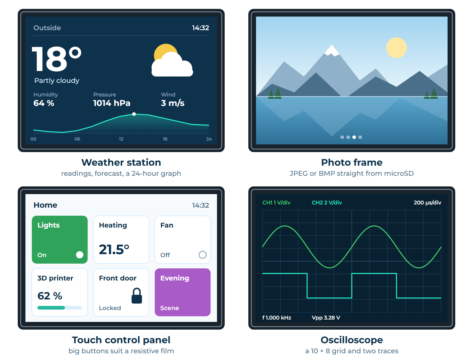
480 × 320 is a comfortable size: large enough for a graph with readable labels, a photo or a row of fingertip-sized buttons, small enough to fill quickly. That is why this class of screen keeps turning up in projects, both on this very shield and on its relatives.
1. A weather station
The most popular build of all. In the Instructables project Second Multi-functional Weather Station, an Arduino Mega carries exactly this kind of 3.5-inch ILI9486 shield together with a DS3231 clock and DHT22 and BMP280 sensors, and uses the shield’s card slot for a photo album of about a thousand pictures converted to BMP. Other builds skip the sensors altogether. On the blog thesolaruniverse, an ESP32 with a 3.95-inch shield of the same design fetches the weather from OpenWeatherMap over Wi-Fi and draws it through the 8-bit bus with TFT_eSPI. An Elektor project from December 2023 does the same on a Makerfabs ESP32-S3 board with a 3.5-inch ILI9488 and reads the Wi-Fi settings and the city from a file on the memory card.
2. A photo frame
The microSD slot makes the shield a picture frame almost by itself. MCUFRIEND_kbv ships a showBMP example that reads BMP files straight from the card on pins 10 to 13 and prints how long each one took to load. On an ESP32, the esp-idf-parallel-tft driver by nopnop2002 shows BMP, JPEG and PNG files on shields of this family and calibrates their touch film too. Transitions such as fades and wipes are where the parallel bus pays off: every step of a transition redraws the whole screen, and a full frame costs 23 ms on this bus against a tenth of a second or more over SPI.
3. A video player
Our own test is the heavy end: MJPEG from a card at 25 fps. For a ready-made starting point, the MJPEG examples of the Arduino_GFX library print the average frame rate and split the time between reading, decoding and drawing, which makes them a handy benchmark for any board. Larry Bank, the author of JPEGDEC, the decoder our player uses, drove an old 3.5-inch ILI9486 Uno shield from an RP2040 through PIO and DMA and played animated GIFs on it; his write-up is called Breathing new life into an old LCD shield.
4. A game console
Games need exactly what this bus is good at: redrawing a lot of pixels many times a second. The ESP32-S3_Uno-nofrendo project runs the nofrendo NES emulator on an Uno-format ESP32-S3 board with an ILI9488 8-bit shield plugged straight in and loads the ROMs from the card; it has no joystick or sound yet. At the simpler end, a Tetris clone for an Arduino Mega with an ILI9486 shield gets its music from a car FM transmitter, so you tune a radio to 87.5 MHz to hear it. The Dumblebots tutorial series builds a Paint program and Tic-Tac-Toe on the same kind of 3.5-inch shield, touch film included.
5. A touch panel on the wall
A smart-home panel is the obvious job for a touch screen of this size, and here the ready-made relatives usually win. The WT32-SC01 Plus combines an ESP32-S3 with a 3.5-inch 480 × 320 screen on the same kind of 8-bit bus. openHASP turns it into an MQTT-controlled panel built on LVGL, and with a community component ESPHome can drive it for Home Assistant. AirQualitySensor-IDF turns the same board into an air-quality monitor: it reads particulate, CO₂, temperature and humidity sensors and draws six hours of history with LVGL. If you have a 3D printer, you may already own a screen of this class: Marlin’s Color UI runs on 3.5-inch 480 × 320 touch screens such as the MKS TFT35, connected to the printer’s STM32 over the FSMC parallel bus.
6. Instruments
A scope trace has to be redrawn many times a second, which suits a fast bus. One open project pairs an STM32F303 with a 3.5-inch ILI9486 display for a 2 Msps oscilloscope with a 4096-point record. DLO-138, open firmware for the popular DSO-138 kit, drives that kit’s smaller ILI9341 over an 8-bit bus and turns it into a two-channel scope with two digital channels on top. For gauges, meters and graphs, TFT_eSPI keeps a whole folder of examples written for 480 × 320.
A few more ideas people have built on 480 × 320 screens:
- An offline GPS navigator. IceNav-v3 draws offline OpenStreetMap maps on an ESP32-S3 and supports ILI9488 panels over SPI and over 8- or 16-bit parallel buses.
- A “now playing” screen. ThingPulse’s Spotify remote shows the album art and matches the background colour to the cover on a 3.5-inch ILI9488.
- A radio with a spectrum view. An all-band receiver built on the Si4735 chip and an ESP32 draws a spectrum and a waterfall on a 4-inch 480 × 320 ILI9488.
Relatives: the same screen in other forms
The shield belongs to a large family. If its form factor or its bus does not suit a project, one of its relatives might. All of them are 480 × 320 except the smaller Uno shields:
| Display | Controller and bus | Worth knowing |
|---|---|---|
| 2.4- and 2.8-inch Uno shields | ILI9341 and others; 8-bit parallel | The same pinout and libraries at 240 × 320 |
| 3.5-inch SPI modules, such as the MSP3520 | ILI9488; 4-wire SPI | Few pins, touch on its own SPI lines, three bytes per pixel |
| 3.95-inch Uno shields | ILI9486 and others; 8-bit parallel | Bigger glass, the same wiring |
| WT32-SC01 Plus | ST7796; 8-bit parallel, ESP32-S3 on board | A finished panel for openHASP, ESPHome and LVGL |
| Makerfabs ESP32-S3 Parallel TFT, 3.5-inch | ILI9488; 16-bit parallel, ESP32-S3 on board | Twice the bus width |
| ESP32-3248S035, the 3.5-inch Cheap Yellow Display | ST7796; SPI, ESP32 on board | Complete and cheap, but SPI |
| MKS TFT35 | ILI9488 or ST7796; FSMC parallel | The touch screen of many 3D printers |
Strengths and weaknesses
| Strengths | Weaknesses |
|---|---|
| Plugs straight into an Uno or a Mega | On an Uno it takes nearly every pin, I²C included |
| 480 × 320 with touch and microSD on one board | ILI9486 or ILI9488: the board doesn’t say which, and it may be write-only |
| An 8-bit bus: a full frame in 23 ms at a verified 20 MHz | Thirteen signal wires on any host it doesn’t plug into |
| Works with 3.3 V hosts: ESP32, RP2040, STM32 | Without a hardware bus peripheral most of the speed is lost |
| Full-screen video at 25 fps from an ESP32-S3 | No tearing-effect signal on the header |
| Touch without an extra chip | The touch film shares pins with the display and needs the host’s ADC |
| A microSD slot on separate SPI lines | The backlight is always on, with no way to dim it |
Bottom line
The 3.5-inch TFT LCD shield looks like a relic of the Arduino Uno era, and on an Uno it behaves like one: it takes nearly every pin and fills the screen at the pace of an 8-bit processor. Give it a host with a proper parallel peripheral, though, and the old bus shows why it has survived: a byte per clock, a full 480 × 320 frame in 23 ms, video at 25 fps.
For a weather station, a photo frame, a control panel or a small instrument that is plenty, as long as the first run starts from a known-good configuration:
- Check 5V, 3V3 and GND for shorts, then connect GND and 5 V into the 5V pin first.
- Wire by the labels on the back, never by position, and hold LCD_RD high from the start.
- Use the ILI9488 sequence, COLMOD 0x66 and MADCTL 0x28 at 10 MHz or less.
- Draw solid fills and gradients first; if the picture is washed out or flickers, try the ILI9486 sequence.
- Raise the clock step by step, up to 20 MHz on an ILI9488.
- Add the touch film and the microSD card last, one at a time.
Everything above and more, in one file: the programming guide for this shield. The pinout by label, bus timing and datasheet limits, initialisation sequences for both controllers, pixel formats, rotation, touch and microSD, a bring-up procedure and a failure guide, with every claim marked as verified, likely or unknown. Hand it to a coding agent before it writes a single line of driver code.