LILYGO TTGO T-Display: the ESP32 That Shows the Result Right Away
An ordinary development board can do a great deal, but it talks to the developer mostly through lines in the Serial Monitor. The LILYGO TTGO T-Display has a more convincing way of doing it: a colour screen on the board itself. Wire up a sensor and you see the readings straight away. Pull data over Wi-Fi and you can draw a graph or a status line. Build a standalone instrument and there is no separate display to add, no power to route to it and no room to find for it inside the enclosure.
That is why the T-Display is more interesting than just another ESP32 board. It is very nearly a finished front panel for a device: a microcontroller, a screen, two buttons, USB-C and single-cell Li-Po charging on one narrow circuit board.
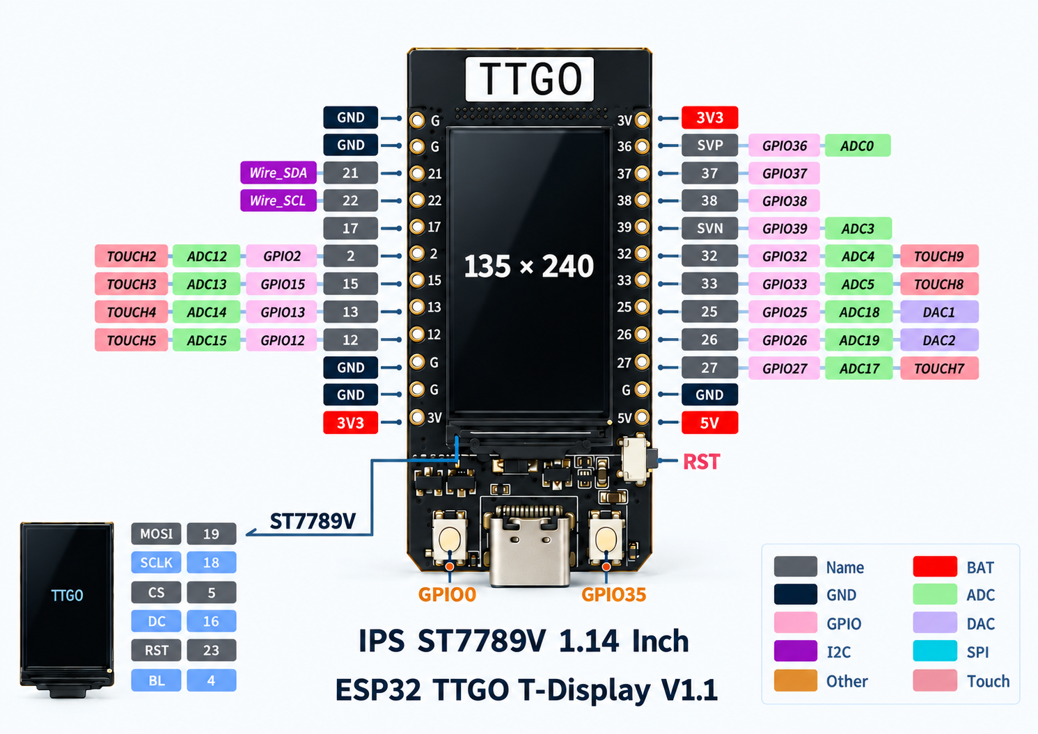
Which board this is about
The name T-Display has grown into a whole family, so the first technical trap is to take the specifications of the wrong model. What follows is about the classic LILYGO/TTGO T-Display on the original ESP32, with a 1.14-inch screen and a resolution of 135 × 240 pixels. This is not the T-Display-S3: the S3 has a different processor, a 1.9-inch screen, a different display connection, different GPIOs and PSRAM.
Current LILYGO documentation lists the SoC of the classic board as ESP32-D0WDQ6. Flash size and the USB-to-UART chip can differ between production batches, so a seller’s description or somebody else’s example code is no substitute for checking the board in your hand.
Specifications
| Part | Specification | What it means in practice |
|---|---|---|
| Microcontroller | ESP32-D0WDQ6 | The classic ESP32, not an S2, S3 or C3 |
| Processor | Two Xtensa LX6 cores, up to 240 MHz | Enough for Wi-Fi, the interface, sensors and background logic at the same time |
| Memory | 520 KB of on-chip SRAM, no PSRAM | Large images and double buffering call for careful memory budgeting |
| Flash | Usually 4 MB; a 16 MB variant exists | The size has to be checked before choosing a partition table |
| Wireless | 2.4 GHz Wi-Fi 802.11 b/g/n; Bluetooth 4.2 BR/EDR and BLE | Suits MQTT, HTTP, ESP-NOW, BLE beacons and talking to a phone |
| Display | 1.14-inch IPS TFT, ST7789V controller | A colour screen with good viewing angles |
| Resolution | 135 × 240 in portrait; usually 240 × 135 in landscape | Good for one large figure, a few status lines or a small graph |
| Display interface | 4-wire SPI; the stock TFT_eSPI profile runs it at 40 MHz | The screen is fast, but it occupies several GPIOs |
| Controls | Two buttons: GPIO0 and GPIO35 | Enough for a menu, page flipping, a confirmation or a wake-up |
| Power | USB-C or a single-cell Li-Po; charging on board | The basis for a portable instrument with no separate charger module |
| Battery monitoring | ADC on GPIO34, sense circuit enabled by GPIO14 | The charge level can be shown right in the interface |
| USB | USB-C through a USB-to-UART bridge | The original ESP32 has no native USB device; the port serves power, flashing and serial communication |
| USB-to-UART | CH9102 on what is currently sold; older revisions used CP210x | When a driver misbehaves, look at the actual VID/PID rather than guessing from the board name |
| Logic levels | 3.3 V; the GPIOs are not 5 V tolerant | A 5 V signal needs level shifting |
| Dimensions | About 51.5 × 25 mm | Noticeably narrower than most “DevKit plus a separate TFT” builds |
| Development environments | Arduino IDE, PlatformIO, ESP-IDF; MicroPython is possible | Arduino is the easier quick start, ESP-IDF the stricter choice for a serious project |
A couple of numbers give a sense of the scale. A full frame in RGB565 takes 135 × 240 × 2 = 64,800 bytes, which is about 63.3 KiB. Two frame buffers are already around 126.6 KiB, before the Wi-Fi stack, the tasks and the application’s own data. That is why partial redraws, modestly sized sprites and updating only the regions that changed are especially useful on this board.
Why the built-in display earns its place
The screen here is useful as a development tool, not as decoration. It shortens the path from a prototype to something you can use without a computer.
- Instant feedback. The device itself shows whether it joined Wi-Fi, what IP address it was given, what the sensor returned and why the actuator did not fire.
- A local interface. Two buttons and a colour screen are enough for a menu, several pages, warnings and simple settings without a mobile app.
- Diagnostics on the spot. If the sensor sits in a distribution board, a greenhouse or on a machine, the key readings are visible next to the equipment and not only in the cloud.
- A compact, finished prototype. Add a battery and an enclosure and the T-Display already looks like a pocket instrument, a remote or a miniature monitoring panel.
- A fast way to show the idea. A client or a colleague finds a live screen of statuses easier to judge than a stream of numbers in a terminal.
The screen sets limits too. It is small and it is not a touchscreen, and six of the ESP32’s signals are already spoken for by the display. A backlight left on all the time makes a noticeable difference to battery life. Complex graphics run short of memory without PSRAM, so the T-Display is at its best not as a tiny smartphone but as a clear interface built from a few well-chosen readings.
What is already wired to the ESP32
| Function on the board | GPIO | What matters |
|---|---|---|
| TFT MOSI | 19 | Data to the ST7789V |
| TFT SCLK | 18 | The display clock line |
| TFT CS | 5 | Display chip select, and an ESP32 boot-strapping pin at the same time |
| TFT DC | 16 | Switches between command and data |
| TFT RESET | 23 | Hardware reset for the display controller |
| TFT backlight | 4 | Can be switched on, switched off and dimmed with PWM |
| Button on GPIO0 | 0 | Also BOOT/strapping: holding it during a reset puts the ESP32 into the bootloader |
| Second button | 35 | Input only; GPIO35 has no internal pull resistors |
| Li-Po measurement | 34 | ADC1, input only |
| Sense circuit enable | 14 | GPIO14 is usually driven high before the battery is read |
It is sensible to treat these pins as taken. SPI does in theory allow several devices to share the MOSI and SCLK lines, but for a first project it is safer to leave GPIO18 and GPIO19 to the screen and put an external SPI bus on free pins.
The headers, pin by pin
The tables below assume the display facing you and the USB-C connector at the bottom.
Left header, top to bottom
| Pin | What it can do | Limits and good uses |
|---|---|---|
| GND | Ground | Two pins in a row |
| GND | Ground | — |
| GPIO21 | Digital input/output | The recommended SDA for I²C |
| GPIO22 | Digital input/output | The recommended SCL for I²C |
| GPIO17 | Digital input/output | One of the least troublesome free GPIOs; fine for UART TX or PWM |
| GPIO2 | ADC2, Touch2, digital I/O | A strapping pin: external circuitry must not force the wrong level at start-up |
| GPIO15 | ADC2, Touch3, digital I/O | Strapping and JTAG; use with care |
| GPIO13 | ADC2, Touch4, digital I/O | Overlaps JTAG, but is usually usable after boot |
| GPIO12 | ADC2, Touch5, digital I/O | Strapping and JTAG; an active external load during reset is especially unwelcome here |
| GND | Ground | Two pins in a row |
| GND | Ground | — |
| 3V3 | 3.3 V power | Not a GPIO |
Right header, top to bottom
| Pin | What it can do | Limits and good uses |
|---|---|---|
| 3V3 | 3.3 V power | Not a GPIO |
| GPIO36 / SVP | ADC1_CH0, digital input | Input only, no internal pull resistor |
| GPIO37 | ADC1_CH1, digital input | Input only, no internal pull resistor |
| GPIO38 | ADC1_CH2, digital input | Input only, no internal pull resistor |
| GPIO39 / SVN | ADC1_CH3, digital input | Input only, no internal pull resistor |
| GPIO32 | ADC1_CH4, Touch9, digital I/O | An excellent general-purpose GPIO, and an analogue input that still works while Wi-Fi is running |
| GPIO33 | ADC1_CH5, Touch8, digital I/O | An excellent general-purpose GPIO, and an analogue input that still works while Wi-Fi is running |
| GPIO25 | ADC2_CH8, DAC1, digital I/O | A true 8-bit DAC; handy as an output, as PWM, or as SCK for an external SPI bus |
| GPIO26 | ADC2_CH9, DAC2, digital I/O | The second true 8-bit DAC; handy as MOSI for an external SPI bus |
| GPIO27 | ADC2_CH7, Touch7, digital I/O | A general-purpose GPIO; handy as MISO for an external SPI bus |
| GND | Ground | — |
| 5V | 5 V power rail | Not a GPIO, and not a sign of 5 V logic |
SVP and SVN are the historical names of the SENSOR_VP and SENSOR_VN analogue inputs, that is GPIO36 and GPIO39. They are not power pins.
How to choose GPIOs without unpleasant surprises
For ordinary digital inputs and outputs the first candidates are GPIO17, 21, 22, 25, 26, 27, 32 and 33. It makes sense to keep GPIO21 and GPIO22 for I²C.
For a second SPI bus, the official LILYGO factory example uses a convenient group:
| External SPI signal | GPIO |
|---|---|
| SCK | 25 |
| MOSI | 26 |
| MISO | 27 |
| CS | 33 |
For analogue sensors with Wi-Fi switched on, choose ADC1: GPIO32, 33, 36, 37, 38 or 39. On the classic ESP32, ADC2 shares a resource with Wi-Fi, so reading GPIO2, 12, 13, 15, 25, 26 or 27 as analogue inputs may simply not work while the radio is running. GPIO36–39, meanwhile, are input only and need an external pull resistor if the sensor or the button relies on one.
There are three more rules that save a particularly large amount of time:
- GPIO0, 2, 5, 12 and 15 are read during reset as strapping pins. Connected peripherals must not force their start-up levels.
- GPIO34–39 are inputs only and have no software
pull-uporpull-down. On the board itself, GPIO34 and GPIO35 are already taken by the battery and by a button. - A load must not be powered straight from a GPIO. A relay, a motor, a solenoid or a high-power LED strip is switched through a transistor, a MOSFET or a driver with whatever protection it needs.
Power and battery life
The board takes power over USB-C and supports a single-cell Li-Po through a 1.25 mm two-pin connector. The cell can be charged on the board, and its voltage measured on GPIO34 once the sense circuit has been enabled with GPIO14. That is convenient for a charge indicator of your own, but a percentage cannot be obtained reliably from a simple linear formula: Li-Po voltage changes non-linearly, and the ADC of the original ESP32 needs calibration.
The T-Display should not be mistaken for an ultra-frugal sensor node just because the ESP32 itself can deep-sleep. Hobbyist measurements of the classic board have produced rough figures of around 66 mA when active, 80–140 mA with Wi-Fi running and roughly 9 mA in light sleep. These are not datasheet guarantees: the result depends on brightness, firmware, supply quality and board revision. The main practical conclusion is to switch the backlight off or dim it, turn the radio off between sessions and wake the device with a button or a timer.
What people build on a T-Display: three telling cases
1. A local Home Assistant screen
One of the most natural uses is to show a temperature, power consumption, the state of the heating or any other Home Assistant entity. In one published project the board displays the oven temperature through ESPHome, but the same template fits the time of the next train, the level in a tank or an internet speed. The value of this case is the minimal hardware: for a fixed panel, the T-Display and USB power are all it takes.
2. A departure board by the door
The open project ttgo-departure-board turns the board into a public transport display. The repository holds 33 firmware variants for networks in 17 countries: the ESP32 joins Wi-Fi, syncs the time over NTP, queries an API roughly every 30 seconds and updates the countdown every second. The two buttons switch stops and control the screen. It is a good example of an interface where 240 × 135 pixels is not too little: if you show only the direction, the line, the platform and the minutes, that is exactly as much information as you need before leaving the house.
3. A tiny wireless monitor
In 2025 a project drew attention by sending a shrunken image of the desktop over Wi-Fi to a compatible T-Display board. The computer compares frames and sends only the pixels that changed, applying batching and RLE. On an almost static picture its author reached up to 60 frames per second, and around 5 frames per second under heavy motion, with latency below 100 ms on a good network. It is not a practical replacement for a monitor, but it is a fine demonstration of how a traffic-saving algorithm can squeeze unexpectedly much out of an ESP32 and a small SPI display. One thing matters here: the project used a compatible TENSTAR board with 16 MB of flash, so that figure cannot be carried over to any LILYGO automatically.
Another popular layer is mini-games. Two buttons, a colour screen and ready-made libraries have produced Space Shooter, Breakout and small handheld builds carrying several games at once. That is entertainment and, at the same time, a decent teaching bench for sprites, frame rate, button handling and memory management.

Four T-Display builds from the channel
The Build Mode channel has built on a T-Display four times so far. In one video the board becomes a Bluetooth speaker: the ESP32 receives music over A2DP, a MAX98357A amplifier drives a small speaker and the screen shows a live spectrum analyzer. In another it reads an MPU-6500 motion sensor over SPI, and a page in the browser turns the readings into a 3D model. In the third it balances a frame on the thrust of a single propeller: an MPU-6500 measures the tilt, and a PID controller on the ESP32 drives the motor through a DRV8833. In the fourth it sits in a 3D-printed case as a level and compass, with an MPU-6500, a BMM150 magnetometer and an 18650 cell.


Pressing play loads the video from YouTube. Privacy Policy
What people look for most often, and why
Four themes repeat in the top results for queries about the classic T-Display: the first run, configuring TFT_eSPI, the pinout, and ready-made projects — clocks, weather, Home Assistant, MQTT panels and games. That is an accurate reflection of the board’s strengths and weaknesses.
People are drawn in by how quickly they can get a good-looking result, and most often they stumble over the configuration of this particular display. TFT_eSPI needs the Setup25_TTGO_T_Display.h profile; it pins down the ST7789V, the 135 × 240 geometry and the correct GPIOs. On alternative stacks you have to account for the offset of the active area of the matrix, the BGR colour order and separate backlight control. A telling failure: the program and the LCD itself can both be working, yet the screen looks black simply because GPIO4 never switched the backlight on.
The minimal Arduino test, once the TFT_eSPI profile has been selected, looks like this:
#include <TFT_eSPI.h>

TFT_eSPI tft;

void setup() {
  pinMode(4, OUTPUT);
  digitalWrite(4, HIGH);

  tft.init();
  tft.setRotation(1);              // 240 × 135
  tft.fillScreen(TFT_BLACK);
  tft.setTextColor(TFT_CYAN, TFT_BLACK);
  tft.drawString("Wi-Fi: OK", 12, 12, 4);
}

void loop() {}
In the Arduino IDE the manufacturer recommends the ESP32 Dev Module profile, a CPU frequency of 240 MHz, QIO, 4 MB of flash for the ordinary version, PSRAM disabled and an upload speed of 921600. If the firmware does not start or the bootloader does not answer, GPIO0 is used as BOOT: hold the button down, tap Reset, release BOOT and try the upload again.
Strengths and weaknesses
| Strengths | Weaknesses |
|---|---|
| A colour IPS panel is already fitted and proven by the design of the board | The screen is small, with no touch layer |
| Wi-Fi, Classic Bluetooth and BLE | An old ESP32 generation: no native USB and none of the newer ESP32-S3 capabilities |
| Two buttons, USB-C, Li-Po charging, battery monitoring | No PSRAM; heavy graphics eat the SRAM quickly |
| More compact than a DevKit plus a separate TFT | The display and the service circuits occupy a noticeable number of GPIOs |
| Arduino, PlatformIO, ESP-IDF, TFT_eSPI and LVGL examples all exist | ADC2 conflicts with Wi-Fi, and GPIO36–39 work as inputs only |
| A good fit for standalone panels and meters | The backlight and Wi-Fi limit how long it runs on a battery |
| Two true DACs on GPIO25/26 and plenty of ADC1 inputs | Revisions differ in flash and USB-to-UART, so the specification of a particular unit has to be checked |
Bottom line
The LILYGO TTGO T-Display is valuable not for record specifications but for a well-judged layout. It turns the invisible work of a microcontroller into an interface you can read: the device reports its state immediately, shows measurements, takes commands from two buttons and can run on a battery.
For a desk clock, a Home Assistant indicator, a portable meter, an MQTT remote, a mini-game or a networked departure board, the classic T-Display remains a very sensible foundation. The main thing is to remember its age and its limits: do not confuse it with the T-Display-S3, do not count on PSRAM, protect the boot GPIOs, use ADC1 while Wi-Fi is active and check the flash size of the particular board. If 240 × 135 pixels and two buttons are enough for the project, the built-in screen saves not only components but the most expensive resource in prototyping — the time between an idea and the first result you can actually see.
Everything above, condensed into a platform-independent hardware reference a coding agent can follow: pin allocation classes, electrical rules, the canonical GPIO matrix and a machine-readable board profile.